
Lighting Pager User Manual


® U.S. Registered Trademark
Copyright © 1998 Honeywell Inc. • All Rights Reserved
CHECKOUT AND TEST
65-0229-1
7800 SERIES
Relay Modules
This publication provides general checkout and troubleshooting procedures for the 7800 SERIES Relay Modules.
SYSTEM CHECKOUT
IMPORTANT
Perform all Static Checkout Procedures in the
applicable relay module installation instructions
before starting these procedures.
WARNING
Explosion Hazard.
Can cause serious injury or death.
Do not allow fuel to accumulate in the combustion
chamber for longer than a few seconds without
igniting to prevent danger of forming explosive mixture
Close manual fuel shutoff valve(s) if flame is not
burning at end of specified time.
WARNING
Electric Shock Hazard.
Can cause serious injury or death.
1. Use extreme care while testing system. Line
voltage is present on most terminal connections
when power is on.
2. Open master switch before removing or installing
7800 SERIES Relay Module or Keyboard Display
Module connector.
Make sure all manual fuel shutoff valve(s) are closed before
starting initial lightoff check and Pilot Turndown tests.
Do not put the system in service until you have satisfactorily
completed all applicable tests in this section and any others
recommended by the original equipment manufacturer..
Limit trial for pilot to ten seconds. Limit the attempt to light
main burner to two seconds after fuel reaches burner nozzle.
Do not exceed manufacturer nominal lightoff time.
CAUTION
Equipment Malfunction or Damage Hazard.
Each relay module type is unique. Using existing
wiring on a relay module change can cause
equipment damage.
Make wiring changes when a relay module is replaced
with a different 7800 SERIES Relay Module to
sequence burner.
IMPORTANT
1. If the system fails to perform properly, note the
fault code, fault message, equipment status, and
sequence time on the display. Then refer to the
Troubleshooting section.
2. Repeat all required Checkout tests after all
adjustments are made. All tests must be satisfied
with the flame detector(s) in their final position.
Equipment Recommended
S7800A Keyboard Display Module
Volt-ohmmeter (1M ohm/volt minimum sensitivity) with:
0-300 Vac capability.
0-6000 ohm capability.
0-10 Vdc capability.
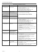
Checkout Summary
Table 1 provides an overview of checkout steps performed for
each applicable system.
See Installation Instructions for location of component parts
and/or Q7800 Specifications for terminal locations.