OIL FURNACE INSTALLATION INSTRUCTIONS MODELS FH085D36E FLF085D36E FLR085D36E FLR140D60E FH110D48E FLF110D48E FLR110D48E FC085D36E FH110D60E FLF110D60E FLR110D60E WARNING READ ALL INSTRUCTIONS CAREFULLY BEFORE BEGINNING THE INSTALLATION. THIS INSTALLATION MUST COMPLY WITH THESE INSTRUCTIONS AND THE REQUIREMENTS OF ALL GOVERNING CODES AND ORDINANCES FOR THE INSTALLATION LOCATION. IT IS THE RESPONSIBILITY OF INSTALLER TO KNOW AND UNDERSTAND ALL OF THESE REQUIREMENTS.
CONTENTS Getting Other Information and Publications ......... 1 Installation and Operating Instructions Equipment Selection ............................................... 2 Locating the Furnace .............................................. 2 Installing the Furnace ............................................. 6 Duct Work ............................................................... 6 Installing a Cooling Unit .......................................... 6 Wiring ...........................................
GETTING OTHER INFORMATION and PUBLICATIONS These publications can help you install the furnace. You can usually find these at your local library or purchase them directly from the publisher. Be sure to consult current edition of each standard. FOR MORE INFORMATION, CONTACT THESE PUBLISHERS: ACCA Air Conditioning Contractors of America 1712 New Hampshire Ave. N.W.
INSTALLATION and OPERATING INSTRUCTIONS EQUIPMENT SELECTION LOCATING THE FURNACE An accurate heating load calculation must be conducted using American Society of Heating, Refrigeration and Air Conditioning Engineers (ASHRAE) or Air Conditioning Contractors of America (ACCA) manuals. Do not add a large safety factor above the calculated value. If the calculated heating load requirement exceeds the heating capacity rating of a given model, use only the next larger size available.
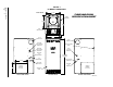
FIGURE 1 FLF/R MODELS DIMENSIONS TABLE 2 FLF/R MODELS DIMENSIONS (INCHES) FLF/FLR 085, 110 AND 140 SPECIFICATION SHEET J TOP VIEW RETURN DUCT SUPPLY DUCT D Plenum Openings Cabinet Model Number Flue Conection A B C DxE DxF G Width Depth Height Supply Return Location Dia. H Air Filters 1 J F LF 085D 36E FLR085D36E 23 23 48.125 36.625 48.125 36.625 22x20 22x20 22x14 22x14 Front Rear 6 6 31.625 5.125 16 x 20 x 1 31.625 5.
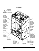
Manual 2100-422 Page 4 FIGURE 2 FH MODELS DIMENSIONS 21 7/8" TOP VIEW SUPPLY OPENING FH085 AND FH110 SPECIFICATION SHEET 19 7/8" 30 1/2" FLUE KNOCKOUT 23" FLUE KNOCKOUT FLUE KNOCKOUT OPTIONAL HIGH VOLTAGE ENTRANCE REAR CLEANOUT DOOR OPTIONAL LOW VOLTAGE ENTRANCE HIGH VOLTAGE ENTRANCE OPTIONAL OIL ENTRANCE 53" (FH085) 59" (FH110) OIL ENTRANCE LOW VOLTAGE ENTRANCE 19 1/4" FRESH AIR KNOCKOUT 16" RETURN OPENING (CUT OUT) LEFT SIDE VIEW OPTIONAL OIL ENTRANCE VESTIBULE DOOR FRONT VIEW RETURN
FIGURE 3 FC085 MODEL DIMENSIONS 21 7/8" FC085 SPECIFICATION SHEET SUPPLY OPENING 19 7/8" 30 1/2" TOP VIEW 23" FLUE KNOCKOUT FLUE KNOCKOUT FLUE KNOCKOUT OPTIONAL HIGH VOLTAGE ENTRANCE 54 1/4" OPTIONAL LOW VOLTAGE ENTRANCE REAR CLEANOUT DOOR LOW VOLTAGE ENTRANCE OIL ENTRANCE HIGH VOLTAGE ENTRANCE OPTIONAL OIL ENTRANCE FRESH AIR KNOCKOUT OPTIONAL OIL ENTRANCE FRONT VIEW LEFT SIDE VIEW RIGHT SIDE VIEW RETURN OPENING 18 1/8" BOTTOM VIEW 19 1/8" MIS-1826 Manual 2100-422 Page 5
INSTALLING THE FURNACE DUCT WORK INSTRUMENTS REQUIRED FOR PROPER SETUP OF THE FURNACE The air distribution system should be designed and installed in conformance with manuals published by Air Conditioning Contractors of America (ACCA) as set forth in Manual D, or ASHRAE publications. It is important that a set of instruments capable of the following requirements be used for the setup of this furnace to ensure proper and safe operation: 1. Oil pump pressure gauge that measures up to 150 PSI. 2.
WIRING FIELD WIRING FACTORY WIRING All wiring must conform to the National Electrical Code and all local codes. A separate fuse or breaker should be used for the furnace. All units are fully factory wired. Multispeed blowers are factory wired on high speed for cooling/manual fan operation. Heating speeds are wired for the largest input and may need lower speed for field installed low input nozzle. If replacement wire is necessary, use 105 degrees C minimum. See electrical data, Table 3.
FIGURE 4 TYPICAL UNIT SETUP FLF UNIT SHOWN WARNING ! TYPICAL UNIT SETUP (FLF UNIT SHOWN) ALL WIRING MUST CONFORM TO THE NATIONAL ELECTRIC CODE AND ALL LOCAL CODES. Left side high voltage (unit power) entrance Inspection door Left side low voltage (thermostat) entrance Right side low voltage (thermostat) entrance Left side oil line entrance for opt. air boot To thermostat and optional A/C unit Left side oil line entrance To power source Oil line (see burner pump inst. for hookup info.
FIGURE 5 TYPICAL FLUE INSTALLATION REQUIREMENTS FRONT FLUE LOWBOY MODEL SHOWN (REPRESENTS ALL MODELS) INSTALLER NOTE: Follow all appropriate standards for installing needed venting system. Thimble Draft Regulator (Be sure to follow installation inst. supplied with regulator). 1/4 inch per 1 foot rise L i n e d 90° Rotatable Flue Box on front flue models (remove appropriate cabinet knockout). Mounting screws located under flue box cover.
OIL LINE PIPING BECKETT AFG OIL BURNER First determine whether the pipe system is to be a single line system or a two line system. All connections must be absolutely air tight or you will have a malfunction of the burner. When installing the piping, a good oil filter should be installed close to the burner. A single line system is recommended for gravity feed.
These controls were selected for their proven high quality, dependability, and serviceability. With proper maintenance this burner assembly will provide many years of reliable service. All units are shipped with the oil burner installed, and with high rate oil nozzle installed designed for use with No. 1 or No. 2 fuel oil. Inspect firepot refractory before firing to be sure it has not been jarred out of position in shipment. Burner air tube must not extend beyond inside surface of firepot.
BECKETT R7184B PRIMARY OPERATIONAL GUIDE Pre-Purge Delay – 15 seconds on delay LED Codes – Flashing 1/2 second on / 1/2 second off – system is locked out or in restricted mode (hard lockout). – Flashing 2 seconds on / 2 seconds off – control is in recycle mode (soft lockout). – ON – CAD cell is sensing flame – OFF – CAD cell is not sensing flame. Ignition Trials – On any given call for heat the control will allow three ignition trials. After the three trials the control will go into a soft lockout mode.
FIGURE 7 ELECTRONIC BLOWER CONTROL THERMOSTAT CONNECTIONS TRANSFORMER 24V SECONDARY CONNECTIONS 3 AMP FUSE HEATING BLOWER OFF DELAY ADJUSTMENT IN SECONDS.
TABLE 4 FURNACE DATA Furnace Installed Standard Field Installed Options 2 1 2 1 2 1 Model Number Noz z le Siz e Input B TU H Heating Capacity B TU H F LF 085D 36E .75 105,000 85,000 .65 91,000 74,000 .55 77,000 63,000 FLR085D36E .75 105,000 85,000 .65 91,000 74,000 .55 77,000 63,000 FLF110D48E 1.00 140,000 113,000 .85 119,000 96,000 NA NA NA FLR110D48E 1.00 140,000 113,000 .85 119,000 96,000 NA NA NA FLF110D60E 1.00 140,000 113,000 .
It should be located as close as possible to the oil burner. Care should be taken to prevent air leakage in the oil suction line. Use continuous runs of copper tubing and use minimum number of joints and fittings. Always use flare fittings. E. Adjustment of Electrodes Adjust ignition electrodes as specified in Figure 10. F. Operate Burner Operate burner, adjust air setting for good flame by visual observation, and run for at least 10 minutes or until operation has stabilized. G.
4. FINAL CHECKS M. Measure Stack Temperature Operating the unit at an excessive firing rate will generate more heat than the heat exchanger can utilize and result in unnecessary heat loss up the chimney. Other causes of excessive heat loss are badly sooted heat exchanger surfaces and excessive draft. The temperature of the flue gas provides an indication of these heat losses. Measure flue temperature by subtracting the room air temperature from the thermometer reading.
FIGURE 8 TYPICAL SMOKE – CO2 CHART WITH ADJUSTMENT RANGE High Air Settings Low Bacharach Smoke Number 8 CO2 Curve from plotted points 6 Plotted point Normal adjustment range 4 Tolerance to "knee" "Best" air setting 2 Plotted point Plotted point "Knee" 0 6 8 12 10 Percent CO2 in Flue Gas 14 Technician's plotting area Bacharach Smoke Number 8 6 4 2 0 6 8 12 10 Percent CO2 in Flue Gas 14 MIS-1827 Manual 2100-422 Page 17
FIGURE 9 PRESSURE GAUGE CONNECTION TO BLEED PORT Remove Bleed Port to attach pressure guage.
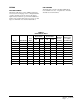
TABLE 5 CORRELATION OF PERCENT OF CO2, O2 AND RESERVE AIR Carbon Dioxide Oxygen Reserve Air (Approx.) 15.4 15.0 14.5 0.0 0.6 1.2 0.0 3.0 6.0 14.0 13.5 13.0 2.0 2.6 3.3 10.0 15.0 20.0 12.5 12.0 11.5 4.0 4.6 5.3 25.0 30.0 35.0 11.0 10.5 10.0 6.0 6.7 7.4 40.0 45.0 50.0 TABLE 6 NO. 2 FUEL OIL EFFICIENCY CHART (NET STACK TEMP. DEGREES F) % O2 200 250 300 350 400 450 500 550 600 650 700 750 800 % O2 1 89.6 88.4 87.3 86.2 85.1 84.0 82.9 81.7 80.6 79.5 78.4 77.3 76.2 14.
SPACING OF ELECTRODES COMBUSTION AIR REQUIREMENTS The electrodes should be spaced 5/32” apart. They should extend 1/16” beyond the end and 5/16” above the center of the nozzle tip as shown in Figure 10. This furnace must be installed in a location where a sufficient supply of combustion air is available for the complete combustion of the fuel oil. Keep in mind that a certain amount of excess air is required as well to ensure complete combustion of the fuel oil.
FIGURE 11 COMBINATION AIR BOOT ASSEMBLY COMBUSTION AIR BOOT ASSEMBLY INTAKE AIR TUBE USE THIS KNOCKOUT FOR OIL LINE BURNER ASSEMBLY REMOVE PUMP TO ASSEMBLE INNER AIR BOOT REMOVE KNOCKOUT IN LEFT SIDE INSERT OUTER AIR BOOT AND SECURE FLANGE TO UNIT MAKE ALL SETTINGS ACCORDING TO MANUAL FOR AIR BOOT.
APPLIANCES LOCATED IN CONFINED SPACES In unconfined spaces in buildings, infiltration may be adequate to provide air for combustion, ventilation, and dilution of flue gases. However, in buildings of unusually tight construction, additional air shall be provided using the method described under “All Air From Outdoors” in Figure 13. An unconfined space (such as an open basement) must have a minimum volume of 50 cubic feet per 1,000 BTUH of total of all appliances in area.
TABLE 9 MINIMUM VENTILATION OPENINGS Model Min. Ventilation Opening Square Inch FH085D36E Recommended Opening (2 Required) Siz e Sq. In. 240 8 x 16 128 FH110D48E 280 9 x 18 162 FH110D60E 280 9 x 18 162 F LF 085D 36E 290 8 x 19 152 FLR085D36E 290 8 x 19 152 FLF110D48E FLF110D60E 340 9 x 19 171 FLR110D48E FLR110D60E 340 9 x 19 171 FLR140D60E 360 9.5 x 19 180 F C 085D 36E 240 8 x 16 128 ALL VENTILATION AIR FROM OUTDOORS A.
FIGURE 14 APPLIANCES LOCATED IN CONFINED SPACES ALL AIR FROM OUTDOORS THROUGH VENTILATED ATTIC NOTE: The inlet and outlet air openings shall each have a free area of not less than one square inch per 4,000 BTU per hour (35 square inches per gallon per hour) of the total input rating of all appliances in the enclosure.
LOUVERS AND GRILLES In calculating free area for ventilation and combustion air requirements, consideration shall be given to the blocking effect of louvers, grilles, or screens protecting openings. Screens used shall not be smaller than 1/4 inch (6.3 mm) mesh and shall be readily accessible for cleaning. If the free area through a design of louver or grille is known, it shall be used in calculating the size opening required to provide the free area specified.
TABLE 10 TEMPERATURE RISE RANGES, LIMIT CONTROL SETTINGS, AND HEATING BLOWER SPEEDS Rise Ranges Maximum Outlet Air Temp. Heating Blow er S p eed .55 .65 .75 70 - 100 70 - 100 60 - 90 200 200 200 Low Low Med FH110D48E .85 1.00 70 - 100 60 - 90 200 200 Low Med Low FH110D60E .85 1.00 60 - 90 60 - 90 200 200 Low Med Low F LF 085D 36E .55 .65 .75 60 - 90 60 - 90 60 - 90 200 200 200 Low Low Med FLF110D48E .85 1.00 60 - 90 60 - 90 200 200 Med Low Med High FLF110D60E .85 1.
AIR FILTERS Only Lo-Boy models are shipped with air filters. Filter kits are available from your local distributor for Upflow and Counterflow models. Knockouts are provided in the sides of the FH series models to facilitate the cutting of the return openings. TABLE 11 FILTER SIZES FOR OIL FURNACES Model The upflow filter kit part numbers are FR23 for a 16x25x1 filter size and FR24 for a 20x25x1 filter size.
LO-BOY MODELS – FILTER LOCATIONS Lo-boy models have the filter installed in the return air cabinet section of the furnace. It is accessible from the rear of the furnace by removing the blower/filter access door. The electrical switch should be turned “off” prior to removing the access door. Refer to Figure 18 below.
MAINTENANCE LUBRICATION No lubrication is required for either the burner or the blower motor. Both are permanently lubricated. INSPECT AIR FILTER Replace filters before each heating season begins. It is recommended that filters also be replaced at least twice during the heating season. Be sure the new filters are set securely in the filter rack so there can be minimal leakage around them.
COMBINATION COMBUSTION CHAMBER/BURNER MOUNTING SYSTEM The furnace has been designed with a combustion chamber mounting system that enables service personnel to remove the combustion chamber, its mounting system, and burner assembly as one unit for inspection and/or service on the bench. It has also been designed to remove the burner assembly independently from the mounting system to perform basic annual service and inspection.
TO REMOVE BURNER ONLY Disconnect fuel line, power cord and wires from T, T on primary control. Loosen (3) 1/4 inch bolts securing burner mounting flange. Twist burner counterclockwise and pull straight back away from the furnace. (See Figure 19.) TO REMOVE THE ENTIRE COMBUSTION CHAMBER MOUNTING SYSTEM Disconnect fuel line, power cord and wires from T, T on primary control. Remove (6) 5/16 inch bolts from around front plate.
COMMON CAUSES OF TROUBLE CAUTION To avoid accidents, always open main switch (OFF position) when servicing the burner. BURNER WILL NOT PRODUCE FLAME Check oil level gauge to see that there is sufficient oil in tank or tanks. Check the burner mounted relay control. Do not adjust this control. Check position of electrodes – incorrect position will cause slow or delayed ignition. Clean electrodes and nozzle. Check and clean strainer in pump. If oil line filter is used, check filter condition.
BLOWER SYSTEM RESISTANCE CHARTS CHART 1 FH085D36E DATA Blow er Speed CHART 4 FLF/FLR085D36E DATA Blow er Speed Blow er Static Blow er Static Low .10 .15 .23 .30 Low .07 .13 .19 .25 Medium .16 .24 .34 .43 Medium .15 .24 .33 .41 High .20 .30 .40 .50 High .20 .30 .40 .50 CHART 5 FLF/FLR110D48E DATA CHART 2 FH110D48E DATA Blow er Speed Blow er Static Blow er Speed Blow er Static Low .03 .08 .13 .18 Low .05 .09 .15 .20 Medium Low .09 .16 .23 .
CHART 8 FC085D36E DATA CHART 7 FLR140D60E DATA Blow er Speed Blow er Speed Blow er Static Blow er Static Low .05 .14 .17 .24 Low .08 .14 .20 .26 Medium Low .08 .17 .22 .30 Medium .16 .24 .36 .42 Medium High .11 .20 .27 .35 High .20 .30 .40 .50 High .20 .30 .40 .
FH SERIES WIRING DIAGRAM IGNITOR CAD CELL BLACK IGNITOR BLACK BURNER MOTOR BLACK BURNER MOTOR BLACK L1 L2 VALVE OIL VALVE WHITE BLACK T T PRIMARY LIMIT CONTROL BACKUP LIMIT BURNER ASS'Y HEAT EXCHANGER AREA UNIT PURPLE PURPLE NOTES 1 IF PRIMARY LIMIT WIRES ARE TO BE REPLACED, USE WIRE WITH INSUL. TEMP. RATING OF 200°C. 2 HEATING SPEED CONNECTION POINT. 3 COOLING SPEED CONNECTION POINT. 4 ONLY ONE HEATING AND COOLING SPEED CAN BE CONNECTED. ALL OTHER TAPS CONNECT TO "SPARE" TERMINALS.
HEAT EX. AREA Manual 2100-422 Page 36 FLF/R SERIES WIRING DIAGRAM PRIMARY LIMIT BACKUP LIMIT 1 BLACK BLACK BLACK BLACK UNIT FLF/R085D36E FLF/R110D48E FLF/R110D60E FLR140D60E FACTORY SETTINGS HTG. BLWR SPD. TEMP. (COLOR) RISE LOW (RED) 60°-90° LOW (RED) 60°-90° MED (BLUE) 60°-90° MED. HIGH (BLUE) 60°-90° MED. HIGH (BLUE) 60°-90° MED. HIGH (BLUE) 60°-90° MED. HIGH (BLUE) 60°-90° GPH INPUT 0.55 0.65 0.75 0.85 1 1.1 1.25 COLING BLWR.
HEAT EX. AREA FC SERIES WIRING DIAGRAM PRIMARY LIMIT 1 BLACK FACTORY SETTINGS HTG. BLWR SPD. TEMP. (COLOR) RISE 0.55 LOW (RED) 60°-90° 0.65 LOW (RED) 70°-100° 0.75 MED (BLUE) 60°-90° UNIT GPH INPUT FC085D36E COLING BLWR. SPEED HIGH (BLACK) HIGH (BLACK) HIGH (BLACK) BLACK PURPLE PURPLE 5 BURNER ASS'Y BACKUP LIMIT 2 BLACK BLACK BLACK BLACK SEC1 SEC2 T87F/Q539A1220 OR EQUIVELANT 24V. CONN. T T L1 4 UNIT FC085D36E 1 2 3 4 BLACK DOOR SWITCH 3 Rc Y G W Rh COND.