
Server User Manual

Back Panel 1-7
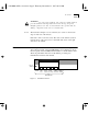
Reset Switch The reset switch is located at the lower left corner of the front panel (see
Figure 1-3 and Figure 1-4). It is recessed to protect it from being pressed
unintentionally. Pressing the reset switch interrupts normal operation,
reinitializes the server, begins the startup sequence, and purges server
RAM in the same way as toggling the power switch. The Self Test LED
lights as the server executes self-test diagnostics. The Boot State LED
lights as the server boots from its software diskette or the network.
CS/2600 Internal
Diskette Drive
Model
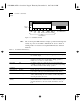
CS/2600 includes a 3.5-inch, 135-tpi diskette drive located on the
right side of the front panel (see Figure 1-4). The drive can
accommodate 1 MB or 2 MB unformatted capacity (720 KB or 1.44 MB
formatted) diskettes. This drive is used for booting system software and
for performing memory dumps following a server failure. The diskette is
also used during operation to maintain software configuration
information.
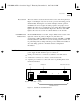
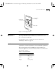
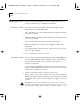
Back Panel
The CS/2500 and CS/2600 back panel, shown in Figure 1-5, contains the
power supply module and three types of connectors:
■
Serial port connectors to connect host, terminal, or modem devices
■
A transceiver connector to connect to local area networks
■
A printer port connector to connect the server to parallel printers with
Centronics interfaces
Figure 1-5 CS/2500 and CS/2600 Back Panel
Fuse
AC power
Power switch
Serial I/O connectors
Transceiver connector
Printer port
Port J0
connector
J1 J3 J5 J7 J9
J8J6J4J2
CS2500BookFile : Overview Page 7 Thursday, December 11, 1997 10:44 AM