
Server User Manual

1-8 C
HAPTER
1: O
VERVIEW
The following sections describe these connectors. Pin assignments are
listed in Appendix A, “Pin Assignments. “
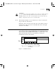
Serial I/O Connectors The back panel provides ten serial I/O ports, labeled J0C through J9C,
using horizontally mounted 25-pin D-series subminiature female
connectors (RS-232-D). All ten ports can be used to connect the server
to hosts, terminal devices, or modems. The communications server acts
as a data communications equipment (DCE) device and can be attached
to a data terminal equipment (DTE) device, such as a terminal, host, or
printer, using a straight-through cable. If you want to connect the server
to a DCE device, such as a modem, use a null modem cable.
You can also have one port serve as the console port. For more
information, see “Console Port” on page 1-8.
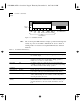
The connector numbers on the back panel correspond to port numbers
used by multiprotocol communications server software (connector J0C
corresponds to port 0, connector J1C to port 1, and so on).
RS-232 Interface
The default serial I/O interface for the CS/2500 series is RS-232-D. For
information about pin assignments, refer to Appendix A, “Pin
Assignments.”
RS-422 Interface
CS/2500 series serial ports also support RS-422 Transmit Data and
Receive Data capabilities. Transmit Data lines are assigned to pins 13
and 14 of the RS-232 serial connectors, while Receive Data lines are
assigned to pins 16 and 19. Pin 25 is used for automatic detection of
RS-422 mode. For complete information on pin assignments, refer to
Appendix A, “Pin Assignments.”
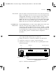
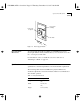
Console Port
You can configure one of the ten serial I/O ports to serve as a console
port. The default is port J0. An asynchronous terminal attached to the
port can be used to:
■
Provide access to the server’s user interface
■
Modify firmware configuration
CS2500BookFile : Overview Page 8 Thursday, December 11, 1997 10:44 AM