
User Guide

TRSM Installation
7
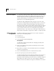
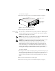
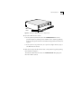
Figure 3
Ground Symbol for Static Discharge
2
Remove the TRSM from its antistatic bag.
3
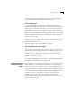
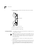
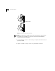
Make sure that the inject handles are in the outward position. See Figure 4.
Figure 4
Handles in Outward Position
4
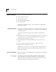
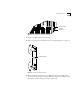
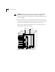
Orient the TRSM to insert it into the LANplex system. For a LANplex 6012
system, orient the module so that its labeling is upright. For a LANplex 6004
system, the module’s labeling should be on your left.
11
12
13
14
15
16
5
6
7
8
4
6
5
4
6
5
RX
TX
RX
TX
RX
TX
RX
A/M
B/M
4
5
Ground symbol
Mounting
screw hole
Module faceplate
Module faceplate