PS520-Series Gas Ovens: English A MIDDLEBY COMPANY owner's operating & installation manual PS520-Series OVENS Model PS520G PS520 (Double) ©2012 Middleby Marshall Inc. PS520 (Single) PS520 (Triple) Part No. 59223 Rev. C Price $30.
NOTICE: This Owner's Operating and Installation Manual should be given to the user. The operator of the oven should be familiar with the functions and operation of the oven. This manual must be kept in a prominent, easily reachable location near the oven. Ovens are shipped from the factory configured for use with natural gas. If permitted by local, national and international codes, at the time of installation the oven may be converted to propane gas operation.
Model No. Modéle No. Serial No. Serié No. Installation Date Date d'installation MIDDLEBY MARSHALL No Quibble Limited Warranty (U.S.A. Only) MIDDLEBY MARSHALL INC. OVEN LIMITED WARRANTY (Non U.S.A.) The Seller warrants equipment manufactured by it to be free from defects in material and workmanship for which it is responsible. The Seller’s obligation under this warranty shall be limited to replacing or repairing, at Seller’s option, without charge, F.O.B.
TABLE OF CONTENTS Page SECTION 1 I. MODEL IDENTIFICATION ...............................................1 SERIES PS520 GAS SPECIFICATIONS..............................2 II. COMPONENT FUNCTION ..............................................4 A. Conveyor Motor and Conveyor Belt .........................4 B. Blower Fan ..................................................................4 C. Gas Burner ..................................................................4 D. Cooling Fan ..............
SECTION 1 DESCRIPTION SECTION 1 DESCRIPTION I. MODEL IDENTIFICATION The Middleby Marshall PS520-Series may be used either as a single oven or stacked for use as double or triple ovens. A single PS520-Series Oven (Figure 1-1) is mounted on a base pad with legs. A double oven (Figure 1-2) consists of two, stacked, single ovens. A triple oven (Figure 1-3) consists of three stacked single ovens. The lower oven is mounted on a base pad with stacking pins.
SECTION 1 DESCRIPTION PS520 SERIES OVEN SPECIFICATIONS Conveyor Belt Width Heating Zone Length Baking Area Square Feet Overall Dimension – Standard Single Oven w/Legs 18.00″ (457mm) 20.00″ (5098mm) 2.5 sq. ft. (0.23 sq. m.) 42.00″ (1067mm) L × 35.21″ (894mm) W × 21.10″ (536mm) H × 42.00″ (1067mm) L × 35.21″ (894mm) W × 36.64″ (931mm) H x 42.00″ (1067mm) L x 35.21″ (894mm) W × 48.19″ (1224mm) H × 250 lb (93.3kg) 325 lb (121.3kg) 22.1 ft3 (0.62 m3) 8.
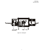
SECTION 1 DESCRIPTION II. COMPONENT FUNCTION (Figure 1-4) Figure 1-4.
SECTION 1 DESCRIPTION II. COMPONENT FUNCTION A. Conveyor Motor and Conveyor Belt The conveyor belt is driven by a variable-speed electric motor (Figure 1-5) operating through a gear reducer. The motor speed is controlled by a digital control. The stainless-steel wire belt can travel in either direction at variable rates ranging from 3 minutes to 30 minutes; this is the time that a product can take to pass through the oven. B. Blower Fan The blower fans are located at the rear of the oven.
SECTION 1 DESCRIPTION Figure 1-6.
SECTION 1 DESCRIPTION F2. Blank Plates 1. Blank Plates- The Blank Plates are available to install on the plenum where an air finger is not required. Half Blank Plate Outer Plate Blank Plate Inner Plate Finger Manifold Assembly Baffle Figure 1-7. Blank Plates (two sizes) and an Air Finger.
SECTION 2 INSTALLATION • SECTION 2 INSTALLATION WARNING - For gas ovens, after any conversions, readjustments, or service work on the oven: Perform a gas leak test. • Test for correct air supply. • Test for proper combustion and gas supply. • Check that the ventilation system is in operation. WARNING Keep the appliance area free and clear of combustibles. WARNING The oven must be installed on an even (level) non-flammable flooring and any adjacent walls must be non-flammable.
SECTION 2 INSTALLATION I. UNLOADING NOTE: The oven, when installed, must be electrically grounded in accordance with local codes, or in the absence of local codes, with the National Electrical Code (NEC), or ANSI/NFPA70. Your Middleby Marshall PS520-Series Oven is shipped partially assembled. It will arrive in a carton on a crate. Carton size for a PS520-Series Oven is: NOTE There must be adequate clearance between the oven and any adjacent combustible construction.
SECTION 2 INSTALLATION ITEM NO. 1 2 3 4 5 6 7 8 PARTS LIST FOR SERIES PS520 Gas OVEN INSTALLATION KIT Double Stack Oven P/N 59183 QTY 2 1 1 4 4 1 1 2 PART NO. 48392 48394 48396 51387 3101908 59223 22450-0228 22361-0001 DESCRIPTION INSULATION BOTTOM TRAY BOTTOM TRAY WELDMENT TOP COVER SCREW MSSLT THREAD 8-32 × 1/2, 18-8 LEG 4″ AD FT OWNER'S OPERATING & INSTALLATION MANUAL GAS HOSE RESTRAINT CABLE GAS HOSE 7 8 ITEM NO.
SECTION 2 INSTALLATION Figure 2-5. MODEL PS520 SINGLE OVEN DIMENSIONS 1 4.00 101.6mm 1 The Opening Height is Adjustable from 2-1/4 inch minimum to 3-3/4 inch maximum in 1/2 inch increments.
SECTION 2 INSTALLATION Figure 2-6. MODEL PS520 DOUBLE OVEN DIMENSIONS 1 4.00 101.6mm 1 The Opening Height is Adjustable from 2-1/4 inch minimum to 3-3/4 inch maximum in 1/2 inch increments. 2 P/N 59927 is shown in its correct installed position.
SECTION 2 INSTALLATION Figure 2-7. MODEL PS520 TRIPLE OVEN DIMENSIONS 1 1 1 The Opening Height is Adjustable from 2-1/4 inch minimum to 3-3/4 inch maximum in 1/2 inch increments. 2 P/N 59927 is shown in its correct installed position.
SECTION 2 INSTALLATION UTILITY ROUGH-IN DIMENSIONS AND POSITIONING FOR PS520-SERIES OVENS WARNING DO NOT USE CONDUIT OR GAS LINE FOR GROUND CONNECTION. CAUTION IT IS RECOMMENDED THAT THE OVEN BE PLACED UNDER A VENTILATION HOOD FOR ADEQUATE AIR SUPPLY AND VENTILATION. ELECTRIC SUPPLY TO BE PROVIDED BY CUSTOMER CIRCUIT BREAKER Figure 2-9. Typical PS520-Series Oven(s) Installation Separate circuit breaker with lockout/tagout electrical shutoff for each oven. Wire each oven separately.
SECTION 2 INSTALLATION These ‘C’ Channel brackets are installed in the vertical plane using existing screws (Item 6) to support these ‘C’ Channels using the upper and lower Key Hole openings in the ‘C’ Channels. The ‘C’ Channels are identical and once installed will allow ample amounts of air through the cooling fan mounted on the rear side of the oven by keeping the oven away from the rear wall. electrical code requirements. Copper is the recommended material for the electrical supply conductors. IV.
SECTION 2 INSTALLATION V. GAS SUPPLY 2. 9. Connect a suitable pressure gauge to pipe line or to outlet pressure tap of gas control concerned, to measure burner pressure (measuring point must be as near to burner as possible). Make sure that the appliance is in operation and the Modu® plus coil is energized with maximum current.
SECTION 2 INSTALLATION Figure 2-16. Gas Burner Assembly G. Gas Burner Maintenance It is recommended to check yearly the minimum and the maximum setting and readjust them if necessary. H. Connection WARNING Some procedures in this section may require conversions, readjustments, or service on the oven's gas system. Before performing these procedures, check that the main gas supply=valve and the circuit breaker/ fused disconnect are in the OFF ("O") position.
SECTION 2 INSTALLATION If the installation will use the supplied gas hose, be sure that the 1/2" to 3/4" gas line fitting is attached. Refer to the instructions in the gas hose package. One gas line connection method is shown in Figure 2-15; however, compliance with the applicable standards and regulations is mandatory. Inlet and regulated gas pressures can be measured using a “U” tube manometer at the tap locations shown in Figures 2-15 and 2-16. 1. Checking the Gas Supply (Inlet) Pressure a.
SECTION 2 INSTALLATION NOTES 18
SECTION 3 OPERATION SECTION 3 OPERATION I. CONTROL FUNCTIONS Figure 3-1. PS520-Series Oven Control Functions WARNING A possibility of injury from rotating parts and electric shock exists in this oven. Never disassemble or clean the oven with the BLOWER switch or any other oven control turned “ON” or “I”. Turn “OFF” or “O” and lockout or tagout all electric power to the oven before attempting to clean or service this oven.
SECTION 3 OPERATION II. COMPONENT INFORMATION AND LOCATION (Figures 3-1 and 3-2) main blower will continue to run after the blower switch is turned to the “OFF” or “O” position. A. Door Safety Switch C. Heat Switch The Door Safety Switch is located at the lower right side of control panel opening. Opening the control panel door permits this switch to open, disconnecting power to all electrical controls. The “Heat Switch” allows the burner to activate.
SECTION 3 OPERATION E. Conveyor The on-off switch for the conveyor motor is on the control panel. Also on the control panel is the digital conveyor speed control. The digital control can be adjusted from 1-10 min. bake time (conveyor speed). Refer to Figure 3-3. Conveyor speed is measured by the amount of time it takes for an item to go through the bake chamber of the oven. MEASURING CONVEYOR SPEED. See Figures 3-4 and 3-5.
SECTION 3 OPERATION 4. Set the temperature controller to the desired baking temperature. WARNING OVEN MUST BE KEPT CLEAR OF COMBUSTIBLES AT ALL TIMES. NOTE: For complete temperature controller operation instructions refer to Step C. 5. Turn the HEAT switch (Figure 3-6) to the “ON” or “I” position. Wait for the “Heat ON” light to turn on. III. STEP-BY-STEP OPERATION A. Startup Procedures 6. Oven will reach a baking temperature of 500°F (232°C) in approximately 20 minutes.
SECTION 3 OPERATION Figure 3-6.
SECTION 3 OPERATION IV. NORMAL OPERATION - STEP-BY-STEP 7. Wait for the oven to heat to the setpoint temperature. Higher setpoint temperatures will require a longer wait. The oven can reach a temperature of 500°F (232°C) in approximately 15 minutes. 8. (Optional) Press the Tem- A.Daily Startup Procedure 1. Check that the circuit breaker/fused disconnect is in the on position. 2. Turn the "BLOWER" ( ) switch to the “ON” ("I") position. 3. Turn the "CONVEYOR" ( ) switch to the “ON” ("I") position.
SECTION 3 OPERATION "HEAT ON" Light Display Lights when the burner is in operation. Shows the Set Point or the Actual Temperature in degrees Fahrenheit (F) or Celsius (C). "SP LOCK" Light Lights when the set point is locked out from changes. This setting can only be changed by service personnel. "SET PT" (setpoint) Light Lights when the set point is shown in the display. OVERTEMP Light "ACTUAL TEMP" Light Lights when the oven temperature is greater than 650°F (343°C).
SECTION 3 OPERATION V. QUICK REFERENCE: TROUBLESHOOTING SYMPTOM light is lit, food product is undercooked Oven will not turn on at all appears in display, oven is not heating Oven will not heat PROBLEM SOLUTION The oven temperature exceeded 650°F (343°C), and the burner was automatically shut down. • Follow the procedures under Daily Shutdown Procedures in this section to shut down the oven.
SECTION 4 MAINTENANCE SECTION 4 MAINTENANCE WARNING Before ANY cleaning or servicing of the oven, perform the following procedure: 1. 2. 3. 4. Switch off the oven and allow it to cool. Do NOT service the oven while it is warm. Turn the full-flow gas safety valve to the off position. Turn off the electric supply circuit breaker(s) and disconnect the electric supply to the oven. If it is necessary to move a gas oven for cleaning or servicing, disconnect the gas supply before moving the oven.
SECTION 4 MAINTENANCE I. MAINTENANCE - DAILY D. Crumb Pans (Figure 4-2) A. Exterior WARNING Everyday you should clean the outside of the oven with a soft cloth and mild detergent. Crumb pan is extremely hot while oven is operating. Allow oven to cool before removing crumb pan. WARNING Never use a water hose or pressurized steam cleaning equipment when cleaning the oven. When the oven is cool remove and clean the crumb pan at each end of the oven.
SECTION 4 MAINTENANCE II. MAINTENANCE - MONTHLY You can order non-caustic cleaner from your local authorized Middleby Marshall Parts Distributor in the quantities listed: NOTE: The oven interior may require cleaning more than once a month depending on the volume of baking. To clean the interior, you have to disassemble some parts of the oven. Part # When cleaning your Series PS520 Oven note the following: Quantity 27170-0244 Case of Quarts (6) 27170-0246 Case of Gallons (4) A.
SECTION 4 MAINTENANCE 6. Remove conveyor as shown. Figure 4-6. Figure 4-4. Figure 4-7. Figure 4-5. CAUTION Be careful not to bump the drive sprocket while handling the conveyor, to avoid damaging the drive shaft.
SECTION 4 MAINTENANCE B. Air Fingers Disassembly For Cleaning 1. As the air fingers are removed use a felt pen to mark all parts of the fingers. This includes the finger manifold, inner plate and the outer plate (refer to Figure 1-9). If a blank or choke plate is used, mark that plate also. Fingers are marked in the order shown; as viewed from the front of the oven. (The marks for an upper oven should be preceded with a “U”, example UB1, UT2, etc.) T1 T2 T3 B1 B2 B3 Standard Fingers 2.
SECTION 4 MAINTENANCE 6. To remove the inner plate, pull the plate out and then up. Figure 4-13. Standard Upper Finger C. Reassembly of Air Fingers 1. Air fingers are made up of one inner plate, one outer plate and the finger housing manifold. Be sure to match up the markings (T1, T2, T3, etc.) on all the parts of the Figure 4-11. 7. The outer finger plate is stainless and may be cleaned by either soaking in a hot, strong detergent solution or using a caustic cleaner.
SECTION 4 MAINTENANCE 4. Replace the air fingers by pushing in at the back side. Remember to replace them according to the numbers marked on them when they were removed. They must go back in the same way they came out. IMPORTANT: When inserting fingers the tab on the outer plate must be in the groove as shown in Figure 4-18. There is a blocking tab on the outside of the groove which will prevent inserting the finger in the groove if the outer plate is moved away from the flange of the finger manifold.
SECTION 4 MAINTENANCE 5. Install fingers and blank plates correctly with edges interlocked and no space between edges. Incorrect - Too Much Space Top Finger Blank Plate Tab on Outer Plate of Finger Located in Groove Incorrect - Too Much Space Top Finger Blank Plate Tab on Outer Plate of Finger Located in Groove Correct - Edges Overlap Completely Top Finger Blank Plate Tab on Outer Plate of Finger Located in Groove Figure 4-18.
SECTION 4 MAINTENANCE D. Reinstall End Plugs 1. Reinstall lower end plug. Be sure to tighten the wing screw on the end plug. 2. Reinstall conveyor. 3. Reinstall upper end plug. Be sure to tighten two wing screws on the end plug. Figure 4-19. Figure 4-20.
SECTION 4 MAINTENANCE E. Conveyor Reassembly Into Oven F. Checking Conveyor Belt Tension 1. Lift conveyor and position it in oven as shown. WARNING NOTE: Conveyor may be inserted into either end of oven. If it is to be installed from the non-drive end of the oven the drive sprocket assembly must be removed as shown in conveyor disassembly section. Oven conveyor belt must be cool when adjusting belt. Do not adjust belt if HOT. 1.
SECTION 4 MAINTENANCE G. Conveyor Belt Link Removal 4. Unhook the link to be removed. 1. Using long nose pliers, an entire link can be removed with the conveyor assembly either in or out of the oven. Position master links at end of conveyor as shown in Figure 4-24. 5. Pull up on the belt link section and remove. Do not discard the link removed as it may be used for making spare master links. NOTE: If a section of the conveyor belt is being replaced it should be done now.
SECTION 4 MAINTENANCE H. Attaching Drive Chain 6. Reconnect the inside master links (Figure 4-29.) 1. If drive sprocket assembly was removed reassemble it into the conveyor drive shaft. Be sure flat on end of drive shaft aligns with set screw in conveyor shaft collar. Once in place tighten 3/32″ set screw. 2. Lift conveyor and install drive chain to conveyor drive sprocket and motor sprocket. Figure 4-29. NOTE: The outside master links have right and left sides to them.
SECTION 4 MAINTENANCE A. Electrical Terminals 4. Reattach conveyor guard to control panel and secure two screws. Open the control cabinet door by removing the three screws from the control cabinet door. Tighten all electrical control terminal screws including the electrical contactor terminal screws as shown in Figure 4-35. Install both upper end plugs. Figure 4-34. Figure 4-35. III. MAINTENANCE - EVERY 3 MONTHS B.
SECTION 4 MAINTENANCE KEY SPARE PARTS KIT parts that can reduce serious downtime and loss of production, if a failure occurs. An oven can be purchased with a Key Spare Parts Kit (Figure 4-36). (The kit can be purchased when the oven is ordered, or later, from a Middleby Marshall Authorized Parts Distributor). The kit contains many of the crucial Replacement parts for this kit can be purchased from your Middleby Marshall Authorized Parts Distributor.
SECTION 5 TROUBLESHOOTING SECTION 5 TROUBLESHOOTING PROBLEM: OVEN BLOWER AND CONVEYOR OPERATE, YET THE OVEN IS NOT HEATING PROBLEM: PRODUCTS ARE OVERCOOKED OR UNDERCOOKED Check for correct setting of conveyor speed control. Check for correct setting on temperature controller. Reset the temperature controller to a new setting (above 200°F), after turning the BLOWER switch to off for 30 seconds. Set the conveyor speed control at correct setting. Turn temperature control to correct setting.
SECTION 5 TROUBLESHOOTING NOTES 42
SECTION 6 ELECTRICAL SCHEMATICS Wiring Diagram, G208-240 50/60 GO, PS520G 59113D SECTION 6 ELECTRICAL SCHEMATICS 43
WARNING Improper installation, adjustment, alteration, service or maintenance can cause property damage, injury or death. Read the installation, operating and maintenance instructions thoroughly before installing or servicing this equipment. NOTICE During the warranty period, ALL parts replacement and servicing should be performed by your Middleby Marshall Authorized Service Agent. Service that is performed by parties other than your Middleby Marshall Authorized Service Agent may void your warranty.