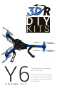
DIY KITS Y6 FRAME KIT Thank you for purchasing a 3DR Y6 DIY Kit! These instructions will guide you through assembling and wiring your new autonomous multicopter.
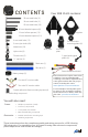
CO NT E NTS Your 3DR Y6 Kit contains: 35 mm steel bolts (3) 30 mm steel bolts (2) 25 mm steel bolts (20) 30 mm threaded spacers (8) 19 mm hollow spacers (13) Top plate Bottom plate 18 mm threaded spacers (12) 6 mm steel bolts (12) Co-axial motor mounting plates (6) 5 mm nylon bolts (40) Metal nuts (23) APM plate Nylon nuts (8) Thumb nuts (5) Accessory plate C-type landing gear plates (6) 11” zip ties (6) Black arm (1) Blue arm (2) Battery straps (2) Six-wire RC receiver cable Two-wire RC receive
You may have opted to also receive: 3DR APM 2.6: 4 mm JP1 jumper connector Telemetry adapter cable 6-position to 5-position GPS cable Radios (2) 6 mm PPM jumper connector 3DR APM 2.
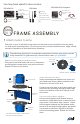
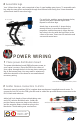
Thread motor cables through arms: Thread the cables from the top motors through the ends of the arms. You’ll want to distinguish between top and bottom motor cables, so use a pen or piece of tape to mark the protruding ends of the top motor cables before threading the bottom motor cables through the arms. Completed motor assembly 2 Install motor collets Attach a threaded collet to the top of each motor using the four small screws included with collets. Apply threadlock to each screw before fastening.
4 Assemble legs Your Y6 has three legs, each comprised of two C-type landing gear pieces. To assemble each leg, align the two pieces and attach through four bottom holes using four 18 mm threaded spacers and eight 5 mm nylon bolts. For each hole, position spacer between holes; secure from each side with nylon bolts. Repeat for all three legs.
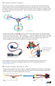
3 Connect motors to ESCs Conect each motor to an ESC using bullet connectors. The order of the bullet connectors doesn’t matter at this point but will become important later when we set motor directions, so make sure you can still access these bullet connectors after assembly is complete. Each ESC should connect to only one motor. Label your ESCs by motor number according to the diagram below.
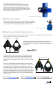
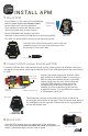
INSTA LL AP M 1 Mount APM Place APM 2.6 in the center of the APM plate with the arrow on the case facing forward (toward wide end). Use four adhesive foam squares to secure the bottom of the case to the plate (one on each corner). 3DR APM 2.6 Ensure arrow on APM points forward! Ensure APM and foam squares are firmly attached so the position of APM does not shift during flight. APM plate For APM 2.5: Mount APM to the top of the accessory plate.
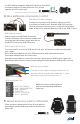
For GPS without compass: Attach GPS board to four holes as shown using four 5 mm nylon bolts, four 30 mm spacers, and four nylon nuts. GPS without compass: 5 mm nylon bolt + 30 mm spacer + GPS + nylon nut 4 Wire additional components to APM 3DR uBlox GPS with Compass: Connect the 6-position to 5-position cable to the GPS 6-position port and to the 5-position APM GPS port (use top-entry port not side-entry port).
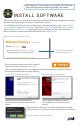
Now that your Y6 assembly is complete, the following steps will get you started configuring your copter. IN STA LL S OF T WA R E Mission Planner is free, open-source software providing multiplatform configuration and fullfeatured waypoint mission scripting for autonomous vehicles. To install Mission Planner on your ground station computer (Windows only), visit ardupilot. com/downloads, select Mission Planner, and select sort by date (short link: goo.gl/Si5grC).
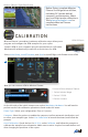
Mission Planner: Flight Data Screen Before flying, complete Mission Planner’s configuration utilities, including RC (shown below), compass, accelerometer, frame type, and flight mode calibrations. Visit planner.ardupilot.com for complete Mission Planner instructions. CALIBRATION Mission Planner’s mandatory hardware calibration steps allow you to program and configure the APM autopilot for your copter. APM USB port Connect APM to your computer using the provided micro-USB cable.
Radio Calibration: Turn on your RC transmitter, select Calibrate Radio, and move all sticks and switches to their extreme positions. Select Click when Done once the red bars are set for all available channels. Show me! Watch videos demonstrating live calibration techniques at 3DRobotics.com/learn. Complete all configuration procedures as described at copter.ardupilot.com before attempting your first flight. MOTO RS & P R O P EL L ER S The diagram below shows the correct rotation direction for each motor.
Ensure that all wires are secured so they will not become entangled in spinning propellers, are not too tight around corners (no hard 90-180 degree bends), and do not pull on the APM or other components. ESCs and wiring secured with zip ties FOLD ING Your Y6 can fold for ease of transport. To collapse the blue arms, remove thumb nuts and bolts from outer holes, and slide blue arms toward black arm. Remove thumb nuts and bolts from outer holes. Flight position Fold.