
User Manual


10
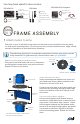
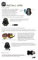
MOTORS & PROPELLERS
Safety Check! Ensure writing on props faces up.
COUNTERCLOCKWISE ROTATION:
USE NORMAL PROPELLER
CLOCKWISE ROTATION:
USE PUSHER PROPELLER
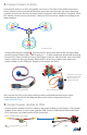
The diagram below shows the correct rotation direction for each motor. Before attaching pro-
pellers, test the motors to ensure the motor rotation is correct.
CCW
!
!
CW
CCW
!
!
CW
CCW
!
!
CW
CCW
!
!
CW
Y6 motor order
Blue arms
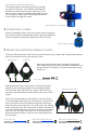
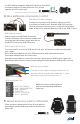
Remove plastic rings from propeller package, select
the one with the larger internal diameter, and insert it
into the back of the propeller hub.
Add propeller to motor collet with writing
facing up in relation to the sky. This means
you’ll need to attach props to bottom motors
upside down! Add the washer and prop nut above
the propeller; tightly fasten prop nut to threaded collet.
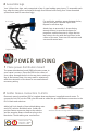
SECURE WIRING
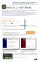
Complete all configuration procedures as described at copter.ardupilot.com
before attempting your first flight.
Show me! Watch videos demonstrating live calibration techniques at 3DRobotics.com/learn.
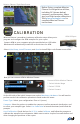
Radio Calibration: Turn on your RC transmitter, select Calibrate Radio, and move all sticks and
switches to their extreme positions. Select Click when Done once the red bars are set for all
available channels.
1. Connection between motor and ESC
2. Switch two wires to reverse motor rotation.
The rotation direction for each motor is determined
by the connections between the motor and the ESC.
To reverse the rotation direction for a motor, switch
two of the three wires connecting the motor and
the ESC.
Your copter includes normal propellers (unmarked
or marked “SF”) and pusher propellers (marked
“SFP” or “P“). Add pusher propellers to motors
marked clockwise, add normal propellers to motors
marked counterclockwise. Use 10-inch props for
top motors and 11-inch props for bottom motors.
Prop nut
Motor
Propeller
Collet
Washer
Before flying, use zip ties to secure ESCs to the frame.