
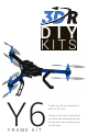
User Manual

1
CONTENTS
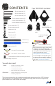
Your 3DR Y6 Kit contains:
Metal nuts (23)
Nylon nuts (8)
5 mm nylon bolts (40)
6 mm steel bolts (12)
25 mm steel bolts (20)
30 mm steel bolts (2)
35 mm steel bolts (3)
11” zip ties (6)
18 mm threaded spacers (12)
19 mm hollow spacers (13)
Thumb nuts (5)
Accessory
plate
APM plate
Top plate
Co-axial motor
mounting plates (6)
C-type landing gear
plates (6)
Black arm (1)
Blue arm (2)
Battery straps (2)
Power distribution board
Bottom plate
30 mm threaded spacers (8)
Double-adhesive foam mounting squares (4)
Two-wire RC receiver cable
Six-wire RC receiver cable
You will also need:
» Phillips screwdriver (small)
» 5.5 mm (7/32) wrench
» 2 mm (5/64) hex wrench
» Blue threadlocking compound
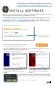
These instructions require some minor
soldering. If you’re unfamiliar with
soldering, our friends at Sparkfun have
some great tutorials that can get you
started, including this comic:
learn.sparkfun.com/curriculum/42.
For an example of exactly what you’ll
be doing for this assembly (soldering
Deans connectors to ESCs), check out
this video: youtu.be/3LJIQeKuLLU.
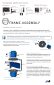
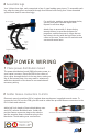
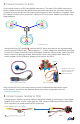
These instructions show the complete assembly and wiring process for a 3DR Y6 using
3DR electronics. For assembling your Y6 Frame Kit using other electronic components,
please adjust these instructions accordingly.
Frame:
Electronics:
» Double-sided foam mounting tape
» Soldering equipment
Threadlocking compound