
User Manual

4
1
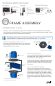
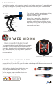
POWER WIRING
Place power distribution board
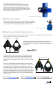
2 Solder Deans connectors to ESCs
The power distribution board (PDB) allocates power to
your copter’s motors. Place the PDB in the center of
your copter through the hole in the top plate, resting on
top of the bottom plate. You may want to experiment
with the orientation of the board to accommodate all
necessary wiring.
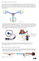
Electronic speed controllers (ESCs) regulate how much power is applied to each motor. To
connect the six ESCs to the PDB, you will need to solder the provided Deans connectors to the
ESCs’ black and red wires.
Add a half-inch length of heat shrink tubing onto
each ESC red wire and black wire. Solder the
positive Deans connector plug to the red wire
and the negative Deans connector plug to the
black wire. Shrink tubing over connections.
Add heat shrink and align wires to correct plugs.
Deans to ESC:
Negative = Black
Positive = Red
-
+
Soldered connectors
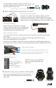
4 Assemble legs
For each hole, position spacer between holes;
secure from each side with nylon bolts.
Repeat for all three legs.
Attach legs to arms with C-shape facing
toward motors (to provide clearance for
propellers on bottom motors). Align the two
top holes in the leg with the two holes in the
center of the arm. Insert two 25 mm bolts and
secure with metal nuts.
Your Y6 has three legs, each comprised of two C-type landing gear pieces. To assemble each
leg, align the two pieces and attach through four bottom holes using four 18 mm threaded
spacers and eight 5 mm nylon bolts.
Leg assembly
25 mm bolts
18 mm
spacers
Metal nuts
5 mm
nylon
bolts
PDB between top and bottom plates