
User Manual

5
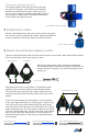
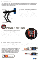
3 Connect motors to ESCs
Starting with the ESC labeled 1 , connect the ESC three-wire cable to the corresponding
position on the PDB pins (M1 - M6 for motors 1 - 6) with orange wire positioned at the top.
Connect ESC Deans connector to any PDB Deans connector. Note that the order of the ESC
Deans connectors does not matter, while the ESC three-wires cables must match the
motor numbers on the PDB pins. Repeat for all motors and ESCs.
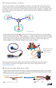
Y6 motor order
Motor connected to ESC
Conect each motor to an ESC using bullet connectors. The order of the bullet connectors
doesn’t matter at this point but will become important later when we set motor directions,
so make sure you can still access these bullet connectors after assembly is complete. Each
ESC should connect to only one motor. Label your ESCs by motor number according to the
diagram below.
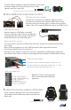
Don’t secure the ESCs to the frame until you have confirmed that each motor spins
in the direction specified in the diagram above (see motor setup instructions at
copter.ardupilot.com).
ESC connected to PDB
Deans
Pins
Motor #
labels
#1
Label ESCs by motor
number; match ESC
motor number to
PDB pin number.
PDB
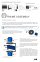
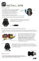
4 Connect power module to PDB
Connect power module 6-position cable to the power module 6-position port. Place power
module in the center of your copter near the PDB. Connect PDB red and black cable (with
XT60 connector) to power module XT60 connectors.
Power module with 6-wire cable