
User Manual

6
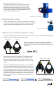
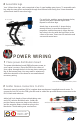
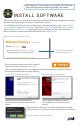
INSTALL APM
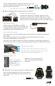
APM plate
Place the GPS module onto the square end of the accessory
plate with the arrow pointing towards the center of the plate. Use
double-sided foam tape to secure case to plate.
3
Mount GPS
Accessory plate
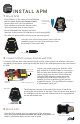
1 Mount APM
Place APM 2.6 in the center of the APM plate
with the arrow on the case facing forward
(toward wide end). Use four adhesive
foam squares to secure the bottom of the
case to the plate (one on each corner).
Ensure APM and foam squares are firmly
attached so the position of APM does not shift during flight.
For APM 2.5: Mount APM to the top of the accessory plate.
3DR APM 2.6
Ensure arrow
on APM points
forward!
Ensure arrow on
GPS points forward!
Locate the PDB six-wire cable (multicolored) and the power module six-position cable (red
and black); thread these cables up through the slots in the APM plate where they can connect
to APM.
APM plate
Using the four holes shown across, insert a 30 mm
threaded spacer over each hole and secure from
below with a 5 mm nylon bolt.
5 mm nylon bolt + 30 mm spacer
The APM plate connects to the ends of the three 35 mm bolts
securing the inside holes of the arms. Place the three outer holes in
the APM plate over the exposed 35 mm bolts on the top plate and
secure with thumb nuts.
APM plate
35 mm bolt + thumb nut
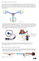
2 Connect APM to power module and PDB
Connect the power module six-position cable
(red and black) to APM’s PM port. Connect the
PDB six-wire cable (multicolored) to the APM
output signal pins (top row). Ensure that the
individual PDB wires are connected to the
corresponding APM output signal pins. For
example, the wire originating in the position
marked M1 (motor 1) on the PDB must connect
to APM output signal pin 1.
PDB to APM wiring
APM output
pin positions
PDB wire
positions