
User Manual

7
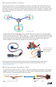
3DR uBlox GPS with Compass:
Connect the 6-position to 5-position cable to the GPS
6-position port and to the 5-position APM GPS port (use
top-entry port not side-entry port). Connect the 4-position
cable to the GPS 4-position MAG port and to the APM I
2
C port.
3DR Radio air module:
Attach antenna to 3DR Radio air module.
Connect telemetry cable to the air module pins
(ensuring that the red wire aligns with the pin
marked 5V) and to the APM Telem port.
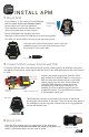
4 Wire additional components to APM
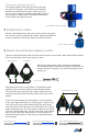
5 Attach accessory plate to APM plate
Place accessory plate onto the four 30 mm spacers
protruding from the APM plate, and secure with four
nylon nuts.
Accessory plate
APM plate
30 mm spacer + nylon nut
GPS without compass: 5 mm nylon bolt + 30 mm spacer + GPS + nylon nut
For GPS without compass: Attach GPS board to four holes
as shown using four 5 mm nylon bolts, four 30 mm
spacers, and four nylon nuts.
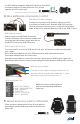
Radio control (RC) receiver:
To connect an RC receiver to APM, use the six-wire and two-wire cables provided with
your copter.
Note: APM also supports one-wire PPM connection with supported receivers.
See copter.ardupilot.com for instructions.
Use the six-wire cable to connect the receiver’s signal pins to APM’s input signal pins.
Use the two-wire cable to connect power and ground pins between APM and the receiver.
APM inputs wiring
APM input pin numbers
Connect six-wire cable to signal pins (top row, “S”).
Connect red wire to power pin (center row, “+”) and
black wire to ground pin (bottom row, “-”).
Match the correct control channel
with its corresponding APM input
signal pin.
6 AUX 2 (OPTIONAL)
5 AUX 1 (MODE SWITCH)
4 YAW / RUDDER
3 THROTTLE
2 PITCH / ELEVATOR
1 ROLL / AILERON
APM Input Signal Pins