
Instruction Manual


Remzibi’s OSD 3DR (with DIY Drones version firmware)
This tutorial is intended to be used with Happy Killmore’s manual (link). This tutorial will cover how to
assemble your Remzibi’s OSD 3DR, and will cover the basic differences in hardware features between
the Original Remzibi’s OSD and the Remzibi’s OSD 3DR with DIY Drones version firmware – including the
Status LED and how to switch between modes – which you will need to following Happy Killmore’s
manual.
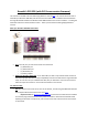
What your Remzibi’s OSD 3DR comes with:
Pins: all of the pins you will need to solder onto the board:
o (1) 3x8 header pins
o (1) 1x20 header pins
o (1) 3x2 header pins
o (1) battery adapter
DIY Drones Remzibi’s OSD cable: It's an FTDI cable, but with a 4-pin female header instead of
the usual 6-pin (this was done to keep compatibility with the OTI cable that the original Remzibi
used). You can also use your standard FTDI cable, but you will have to use some extra wires to
make the required connections. This will be covered later in the tutorial.
You will also need:
GPS Any GPS that uses serial can be used. In this tutorial, I will be using the MediaTek GPS with
basic adapter offered at the DIY Drones store here.
Important note: the DIY Drones Mediatek GPS comes with custom DIY Drones firmware
and must be programmed with the factory default firmware to work with the Remzibi’s OSD.
Updating the firmware is simple to do, and instructions for how to do this will be covered later
in this tutorial.