Instructions and Parts List Important Safety Information TM 3M-Matic 800a Type 39600 Adjustable Read Important Safeguards, pages 3-5 and also operating "Warnings", page 16 BEFORE INSTALLING OR OPERATING THIS EQUIPMENT. Case Sealer with AccuGlide II TM Taping Heads Spare Parts Serial No. It is recommended you immediately order the spare parts listed on page 35. These parts are expected to wear through normal use and should be kept on hand to minimize production delays.
Replacement Parts and Service Information To Our Customers: This is the 3M-Matic™/AccuGlide™/Scotch™ brand equipment you ordered. It has been set up and tested in the factory with "Scotch" brand tapes. If technical assistance or replacement parts are needed, call or Fax the appropriate number listed below. Included with each machine is an Instructions and Parts List manual. Technical Assistance: 3M-Matic™ Helpline – 1-800/328 1390.
Replacement Parts And Service Information To Our Customers: This is the 3M-Matic™/AccuGlide™/Scotch™ brand equipment you ordered. It has been set up and tested in the factory with "Scotch" brand tapes. If any problems occur when operating this equipment, and you desire a service call, or phone consultation, call, write or Fax the appropriate number listed below. Included with each machine is an Instructions and Parts List manual.
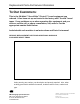
Instruction Manual 800a, Type 39600 Adjustable Case Sealer This instruction manual is divided into two sections as follows: Section I Section II Includes all information related to installation, operation and parts for the case sealer. Includes specific information regarding the AccuGlide™ II STD 2 Inch Taping Heads. Table of Contents Page Section I – 800a Adjustable Case Sealer Description .................................................................................................................
Table of Contents (Continued) Page Maintenance ...................................................................................................................................... Cleaning ............................................................................................................... Lubrication ........................................................................................................... Knife Replacement, Taping Head ........................................................
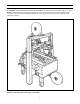
Description TM TM The 3M-Matic 800a Adjustable Case Sealer with AccuGlide II Taping Heads is designed to apply a “C” clip of Scotch brand pressure-sensitive film box sealing tape to the top and bottom center seam of regular slotted containers. The case sealer is manually adjustable to a wide range of box sizes (see "Box Weight and Size Capacities", page 8).
Equipment Warranty and Limited Remedy: THE FOLLOWING WARRANTY IS MADE IN LIEU OF ALL OTHER WARRANTIES, EXPRESS OR IMPLIED, INCLUDING, BUT NOT LIMITED TO, THE IMPLIED WARRANTY OF MERCHANTABILITY, THE IMPLIED WARRANTY OF FITNESS FOR A PARTICULAR PURPOSE AND ANY IMPLIED WARRANTY ARISING OUT OF A COURSE OF DEALING, A CUSTOM OR USAGE OF TRADE: TM 3M sells its 3M-Matic 800a Adjustable Case Sealer, Type 39600 with the following warranties: 1.
Important Safeguards The "Warning – Hazardous Voltage" label, shown in Figure 1-2, is attached to the cover of the electrical box. The label warns service personnel to unplug the power supply before attempting any service work on the case sealer. This safety alert symbol identifies important messages in this manual. READ AND UNDERSTAND THEM BEFORE INSTALLING OR OPERATING THIS EQUIPMENT.
Important Safeguards (Continued) The "Stop" and "Off/On" labels, are attached next to the switches as shown in Figure 1-4. These labels remind operators and casual personnel of the function of these switches. The "Operating Notice" label, shown in Figure 1-6, is located on top of both drive belt assemblies to remind operators of belt adjustment procedures.
Important Safeguards (Continued) The "Tape Threading Label", shown in Figure 1-9, is attached to the left side of both upper and lower taping heads. This label provides a convenient tape threading diagram. More detailed tape loading and threading information is provided in this manual in the set-up procedure section. The following two labels are located on the upper and lower taping heads. Replacement part numbers for these two labels are listed in Section II.
THIS PAGE IS BLANK 6
Specifications 5. Tape Width: 1. Power Requirements: Minimum – 36 mm [1-1/2 inches] Maximum – 48 mm [2 inches] Electrical – 115 VAC, 60 Hz, 3.8 A These machines are equipped with an 2.4 m [8 foot] standard neoprene covered power cord and a grounded plug. 6. Tape Roll Diameter: Contact your 3M Representative for power requirements not listed above. Up to 405 mm [16 inches] maximum on a 76.2 mm [3 inches] diameter core. (Accommodates all system roll lengths of Scotch brand film tapes.) TM 2.
Specifications (Continued) 9. Box Weight and Size Capacities: Weight Note: The case sealer is designed to accommodate most boxes complying with the 1976 FBA and PMMI*** voluntary standard "Tolerances for Top Opening" regular slotted corrugated containers (RSC). Two of the requirements of the standard are the following: Maximum – up to 38.6 kg [85 pounds] Minimum – contents must support top flaps and weight must be sufficient to hold bottom flaps fully closed.
Specifications (Continued) Machine Dimensions W L Minimum mm [Inches] 980 [38-1/2] 920 [36-1/4] Maximum mm [Inches] --- H A 1395 [55] 460 [18] 2185 [86] * -- B C 610 [24] * 105 [4-3/16] 890 [35] * -- F 620 [24-1/2] -- * With outer columns relocated to upper position, "H" maximum dimension increases 100 mm [4 inches] and "B" minimum dimension decreases by 90 mm [3-1/2 inches]. (See "Special Set-Up Procedure", page 27.) Weight – approximate 176.9 kg [390 pounds] crated approximate 158.
THIS PAGE IS BLANK 10
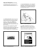
Installation and Set-Up Receiving And Handling After the machine has been uncrated, examine the case sealer for damage that might have occurred during transit. If damage is evident, file a damage claim immediately with the transportation company and also your 3M Representative. 5. Cut cable ties that secure upper assembly to machine bed on each side of machine. 6. Install height adjustment crank handle on top of left column as shown in Figure 2-1A. 7.
Installation and Set-Up (Continued) Figure 2-1 – 800a Frame Set-Up 12. Check for free action of both upper and lower taping heads. 14. Ensure that the tape drum bracket assembly, located on the lower taping head, is mounted straight down, as shown in Figure 2-2A. The tape drum bracket assembly can be pivoted to provide tape roll clearance in certain cases. WARNING – Keep hands/fingers away from tape cut-off knife under orange knife guard. Knife is extremely sharp and can cause severe injury. 15.
Installation and Set-Up (Continued) TAPE DRUM BRACKET (Lower Taping Head) Outboard tape roll mounting (Alternate Position) – Remove the tape drum bracket assembly, stud spacer and fasteners from the taping head. Install and secure on the infeed end of the lower frame, as shown in Figure 2-2B. MACHINE BED HEIGHT Adjust machine bed height. The case sealer is equipped with four adjustable legs that are located at the corners of the machine frame.
Installation and Set-Up (Continued) Use of an extension cord is not recommended. However, if one is needed for temporary use, it must have a wire size of AWG 16 [1.5 mm dia], have a maximum length of 30.5 m [100 ft], and must be properly grounded. DRIVE BELT HEIGHT The drive belt assemblies can be raised 50 mm [2 inches] to provide better conveying of tall boxes. Refer to page 26, "Special Set-Up Procedures – Drive Belt Assembly Height", for set-up procedure.
Operation IMPORTANT – Before operating the case sealer read all the "Important Safeguards", pages 3-5 and "Warnings", on page 16 as well as all of the "Operation" instructions. Refer to Figure 3-1 to acquaint yourself with the various components of the case sealer and also see Section II, page 6, for taping head components.
Operation (Continued) WARNINGS 1. Turn electrical supply off and disconnect before servicing taping heads or performing any adjustments or maintenance on the machine. 2. Turn electrical supply off when machine is not in use. 3. Before turning drive belts on, be sure no tools or other objects are on the machine bed. 4. Keep hands and loose clothing away from moving belts. 5. Never attempt to work on any part of the machine, load tape or remove jammed boxes from the machine while machine is running. 6.
Operation (Continued) Box Size Set-Up 1. ADJUST DRIVE BELTS (Figure 3-2) Place a product filled box on infeed end of machine bed with top flaps folded as shown and manually move box forward to contact lower taping head applying roller. Turn drive belt adjustment crank to position both side drive belts against sides of box. Figure 3-2 – Side Drive Belts 2. ADJUST UPPER TAPING HEAD (Figure 3-3) Turn height adjustment crank to position upper taping head onto box.
Operation (Continued) 3. POSITION COMPRESSION ROLLERS (Figure 3-4) The top flap compression rollers have an adjustable slide mounting to provide side compression through the full range of box widths. Manually move box forward so front of box is aligned with top flap compression rollers. Adjust the compression rollers against top edge of box and tighten knobs to secure rollers in operating position. CAUTION – Hands can be injured or caught between compression rollers and box.
Operation (Continued) Box Sealing 1. Feed boxes to machine at minimum 455 mm [18 inch] intervals. 2. Turn electrical supply "Off" when machine is not in use. 3. Reload and thread tape as necessary. 4. Be sure machine is cleaned and lubricated according to recommendations in "Maintenance" section of this manual. Notes 1. Machine or taping head adjustments are described in "Adjustments", Section I for machine or Section II for taping heads. 2.
Maintenance The case sealer has been designed for long, trouble-free service. The machine will perform best when it receives routine maintenance and cleaning. Machine components that fail or wear excessively should be promptly repaired or replaced to prevent damage to other portions of the machine or to the product. Figure 4-1 illustrates the frame points which should be lubricated every 250 hours of operation. Lubricate the rotating and pivoting points, noted by ) with SAE #30 non-detergent oil.
Maintenance (Continued) WARNING – Turn off electrical power and disconnect power cord from electrical supply before beginning maintenance. If power cord is not disconnected, severe injury to personnel could result. Circuit Breaker The case sealer is equipped with a circuit breaker which trips if the motors are overloaded. Located inside the electrical enclosure on the side of the machine frame just below the machine bed, the circuit breaker has been pre-set at 2.2 amps and requires no further maintenance.
Maintenance (Continued) Figure 4-3 – Box Drive Assembly, Infeed End 6. Install the new belt around drive rollers and insert new pin. Pin must not extend beyond edge of belt. 7. To set drive belt tension, turn adjustment screws (G) equally on both the upper and lower tension assemblies. Turn the screws clockwise to increase tension or counterclockwise to decrease tension. See Figure 4-3.
Adjustments WARNING – Turn off electrical power supply and disconnect power cord from electrical supply before beginning adjustments. If power cord is not disconnected, severe injury to personnel could result. Drive Belt Tension Tension adjustment of the drive belts may be required during normal operation. Belt tension must be adequate to positively move the box through the machine and they should run fully on the surface of the pulleys at each end of the frame.
THIS PAGE IS BLANK 24
Special Set-Up Procedure WARNING – Turn off electrical power and disconnect power cord from electrical supply before beginning special set-up procedure. If power cord is not disconnected, severe injury to personnel could result. Changing Tape Leg Length (From 70 to 48 mm [2-3/4 to 2 Inches]) The following changes to the case sealer will allow taping boxes 90 mm [3-1/2 inches] minimum height. CASE SEALER FRAME (Refer to Figure 5-1A) 1. Raise the upper head assembly (by turning crank handle counterclockwise).
Special Set-Up Procedure (Continued) WARNING – Turn off electrical power and disconnect power cord from electrical supply before beginning special set-up procedure, if power cord is not disconnected, severe injury to personnel could result. Drive Belt Assembly Height The drive belt assemblies can be raised 48 mm [2 inches] to provide better conveying of tall boxes. This change increases the minimum box height that can be taped to 190 mm [7-1/4 inches]. DISASSEMBLE – Figure 5-2 1.
Special Set-Up Procedure (Continued) To Re-position the outer columns: WARNING – Turn off electrical power and disconnect power cord from electrical supply before beginning special set-up procedure, if power cord is not disconnected, severe injury to personnel could result. 1. Remove special nut from the bottom of each column lead screw. Figure 5-4A. 2. Remove plastic column cap from the top of each outer column as shown in Figure 5-4B. 3. Crank upper assembly up, out of plastic nuts.
Special Set-Up Procedure (Continued) Figure 5-4 – Upper Frame Removal 28
Special Set-Up Procedure (Continued) 4. Remove M6 x 16 hex hd screw, special washer and drive belt width adjustment crank. Figure 5-5. Important – Before removing chain, mark both front and rear sprockets/chain with chalk or paint to be sure sprockets/chain when re-assembled, will be in same position as before disassembly. Figure 5-6A and B. Do not rotate sprockets once chain is removed. (This would result in the right and left drive assemblies not being parallel.) 5.
Special Set-Up Procedure (Continued) 7. Remove fasteners (M8 x 16 socket head screws and M6 plain washers) that attach column spacers to machine bed and remove spacers/ outer columns from machine bed. Figure 5-7A. Note – When installing upper assembly back into machine (removed in Step 3), slide upper assembly down into outer columns until lead screws contact plastic nuts and support upper assembly.
Troubleshooting The Troubleshooting Guide lists some possible machine problems, causes and corrections. Also see Section II, "Troubleshooting", pages 15 and 16 for taping head problems. Troubleshooting Guide Problem Cause Correction Drive belts do not convey boxes Narrow boxes Check machine specifications. Boxes are narrower than recommended, causing slippage and premature belt wear.
THIS PAGE IS BLANK 32
Electrical Diagram WARNING – Turn off electrical power supply and disconnect power cord from electrical supply before beginning service. If power cord is not disconnected, personnel could be exposed to dangerous voltages. Severe injury or equipment damage could result.
THIS PAGE IS BLANK 34
Spare Parts/Tools Spare Parts The following parts periodically require replacement due to normal wear. They should be ordered immediately and kept on hand to keep the case sealer in production. 800a Adjustable Case Sealer, Type 39600 Qty Section/Ref. No.
Options/Accessories For additional information on the options/accessories listed below, contact your 3M Representative.
Replacement Parts Illustrations and Parts List 800a Adjustable Case Sealer, Type 39600 With AccuGlide™ II STD (2 Inch) Taping Heads 1. Refer to first illustration, 800a Assembly, for the Figure Number that identifies a specific portion of the machine. 2. Refer to the Figure or Figures to determine the individual parts required and the part reference number. 3. The parts list that follows each illustration, includes the part number and part description for the parts in that illustration.
THIS PAGE IS BLANK 38
800a Adjustable Case Sealer W/AccuGlide™ II STD (2 Inch) Taping Heads 800a Assembly 39
800a Adjustable Case Sealer Figure 2799 40
Figure 2799 Ref. No. 3M Part No.
800a Adjustable Case Sealer Figure 3269 42
Figure 3269 Ref. No. 3M Part No.
800a Adjustable Case Sealer Figure 5350 44
Figure 5350 Ref. No. 3M Part No.
800a Adjustable Case Sealer Figure 5817 46
Figure 5817 Ref. No. 3M Part No. Description 5817-1 78-8094-6379-3 Support – Box 5817-2 78-8113-6759-4 Box – W/English Language Label 5817-3 78-8094-6381-9 Screw – Soc Hd, Hex Hd, M4 x 15 5817-4 78-8005-5740-3 Washer – Plain, 4 mm 5817-5 26-1003-6914-4 Nut – Plastic Insert, M4 5817-6 78-8076-4715-7 Cord Grip 5817-7 78-8076-5211-6 Set Nut – GMP 13.
800a Adjustable Case Sealer Figure 6162/1 of 2 48
Figure 6162 (page 1 of 2) Ref. No. 3M Part No.
800a Adjustable Case Sealer Figure 6162/2 of 2 50
Figure 6162 (page 2 of 2) Ref. No. 3M Part No.
800a Adjustable Case Sealer Figure 6163/1 of 2 52
Figure 6163 (page 1 of 2) Ref. No. 3M Part No.
800a Adjustable Case Sealer Figure 6163/2 of 2 54
Figure 6163 (page 2 of 2) Ref. No. 3M Part No.
800a Adjustable Case Sealer Figure 6164/1 of 2 56
Figure 6164 (page 1 of 2) Ref. No. 3M Part No.
800a Adjustable Case Sealer Figure 6164/2 of 2 58
Figure 6164 (page 2 of 2) Ref. No. 3M Part No.
800a Adjustable Case Sealer Figure 6165 60
Figure 6165 Ref. No. 3M Part No. Description 6165-1 78-8113-6870-9 Cross Bar – Lower, W/English Language Label 6165-2 26-1003-7957-2 Screw – Soc Hd Hex Hd, M6 x 16 6165-3 78-8100-1042-7 Washer – /15 x 6.
800a Adjustable Case Sealer Figure 6166 62
Figure 6166 Ref. No. 3M Part No.
800a Adjustable Case Sealer Safety and Information Labels 64
800a Safety and Information Labels A label kit, part number 78-8113-6744-6, is available as a stock item. It contains all the safety and information labels used on the case sealer, or labels can be ordered separately from the following list. Ref. No. 3M Part No.