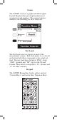
Dynatel™ 965DSP Series Subscriber Loop Analyzers Instruction Manual Includes Spectrum Analyzer (optional) and Active ADSL Modem (optional) June 2005 78-8130-7429-7-F
Welcome to the Instruction Manual for the 3M™ Dynatel™ 965DSP Series of Subscriber Loop Analyzers. The 965DSP Series includes the 965DSP, 965DSP/ADSL, 965DSP/SA and 965DSP/ADSL/SA Loop Analyzers. This document will give you a brief overview of the products, a description of their test functions, and some technical hints on how to find problems on telecommunications cables.
Table of Contents Out of the Box .......................................................4 Front Panel .............................................................5 Control Keys .....................................................6 Editing ...............................................................6 Function Keys ...................................................7 Welcome ................................................................
Out of the Box What you will find when you unpack the shipping box: • 3M™ Dynatel™ 965DSP Series Subscriber Loop Analyzer • Carrying case • NiMH battery pack (inside the 965DSP) • Spare battery holder • Test Leads (red/black pair, blue/yellow pair, green) • Shorting strap • AC charger • Power cord • Instruction manual • Quick card and Warranty card • Self-test board Visually inspect all components.
Screen The 965DSP screen is a graphical LCD (Liquid Crystal Display) that gives high resolution for viewing text and graphics. The screen format is similar to the following for most functions. Test Leads The Test Lead icons are shown on each of the measurement screens. Each lead points to a color dot on the front label that corresponds to the actual test lead. The test leads have the labels “RNG” (ring), “GND” (ground) and “TIP” (tip) for the US and Canada.
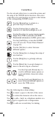
Control Keys Use the red and yellow keys to control the actions and the setup of the 965DSP and its functions. The active control keys for each function are shown at the bottom of the corresponding 965DSP screen. Use the [Return] key to return to a previous step in a function. Use the [Contrast] key to adjust the contrast or to turn the backlight on or off. Use the [Save] key for saving Autotest results, Single Trace TDR waveforms, and ADSL Modem link information (/ADSL option only).
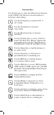
Function Keys Use the blue keys to select the different test functions in the 965DSP. The blue keys become number or letter keys when editing. Use the [Voltage] key to measure DC or AC voltage. Use the [Current] key to measure loop current. Use the [Resistance] key to measure resistance. Use the [Toolbox] key to access: Self-Cal, Load Coils, Kick Test, Ringers, Special and Ground Resistance, K-Test, Ohms/Distance, Stored Results, Caller ID, and Splice Locate.
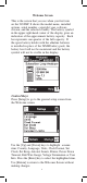
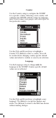
Welcome Screen This is the screen that you see when you first turn on the 965DSP. It shows the model name, installed options, serial number, copyright year, software version, and the selected country. The battery symbol in the upper right-hand corner of the display gives an indication of the approximate battery capacity. Each bar represents one-quarter of the full capacity.
Country Use the Country setup to configure the 965DSP for a specific country. Selecting a new country will configure the 965DSP with the setups for language, units, clock format, wire gauges, and cable types for that particular country. Use the [Up] and [Down] keys to highlight a Country. Use [Enter] to select a country. You will be warned about changing country-specific default values and asked to confirm or cancel your selection. Language Use the Language setup to change only the language in the 965DSP.
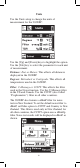
Units Use the Units setup to change the units of measurement for the 965DSP: Use the [Up] and [Down] keys to highlight the option. Use the [Tab] key to select the parameter for each unit of measurement. Distance: Feet or Meters. This affects all distances displayed in the 965DSP. Degrees: Fahrenheit or Centigrade. This affects all temperatures used in the 965DSP. Filter: C-Message or CCITT. This affects the filter used in the Noise function. Use the C-Message filter in the US and Canada.
TDR: Vp (Velocity of Propagation) or m/µS (meters per microsecond). This affects the TDR “velocity of propagation.” Use “Vp” in the US and Canada. Use “m/µS” in other countries. Use the [Enter] key to accept any changes and return. Use the [Return] key to return to the Welcome Screen without making changes. Clock Format Use the Clock Format setup to change the format of the clock. The clock is used for the timestamp and datestamp in stored results.
Set Clock Use the Set Clock setup to change the date and time. Use the [Tab] key to select either the date, time, or a.m./p.m. Use the [Left] and [Right] keys to select the digit to change. Use the blue keys to enter the values. Use the [Up] and [Down] keys to select a.m. or p.m. Use [Enter] to accept the changes and return. Use [Return] to return to the Welcome Screen without making changes. Set Beep Use the Set Beep setup to turn the key beeps on or off. Use the [Tab] key to toggle between on or off.
Autotest Limits Use the Autotest setup to change the pass/fail threshold values for the Inactive Pair, Active Pair and Wideband Autotests. Use the [Up] and [Down] keys to highlight the desired Autotest parameters to modify. Press the [Enter] key to select the highlighted choice or press the [Setup] key to restore the factory default values for the selected Autotest. If Wideband is selected, a list of the available wideband services is displayed.
When the Inactive Pair, Active Pair or specific Wideband service is selected, the Threshold Limits screen will be displayed. This screen displays a list of measurements performed in the selected Autotest and the corresponding pass/fail limits for each measurement. The limits indicate the values at which the measurement result passes (OK), is marginal (Yield Sign) or is unacceptable (Stop Sign). The lower limit threshold value is shown in the box on the left, the upper limit in the box on the right.
A custom Loss Frequency (sometimes known as the “Nyquist frequency”) can be set for use in the Wideband Autotest. The custom Loss Frequency edit screen is accessed by pressing the [Setup] key from the startup screen, selecting Autotest Limits, then Wideband. Press the [Enter] key to select a service type. Select Loss Frequency, then use the [Tab] key to edit. Enter the frequency value in KHz with the blue numeric keys. Use the [Up] or [Down] arrow keys to add or remove digits.
Power Down Timeout To change the power down timeout, press the [Setup] key from the Welcome screen, then select Power Down Timeout. Use the [Up] and [Down] arrow keys to select the desired timeout period, then press the [Enter] key to set that period as the default. After a period of inactivity equal to the default period, the unit will beep, then automatically power down.
Edit Wire Gauge This function allows you to set up custom wire gauges to be used wherever the set uses a wire gauge menu. Press the [Setup] key from the Welcome screen, use the [Down] arrow key to scroll to Edit Wire Gauge, and then press the [Enter] key to edit. Name the custom configuration Custom 1 or Custom 2 by pressing the [Up] or [Down] arrow key. Use the [Tab] key to select the values to be edited. Use the [Left] and [Right] or [Up] keys to select the digit to change.
Voltage Termination (supported countries only) This option allows you to select the input impedance of the 965DSP digital voltmeter. Press the [Setup] key from the Welcome screen, use the [Down] arrow key to scroll to Voltage Termination, and then press the [Enter] key to select. The input impedance of the internal 965DSP voltmeter is normally 1Mohm. However, some legacy systems use voltage measurement systems with input impedances of 100Kohms.
If 100Kohm termination is selected, the 965DSP will display ‘100K’ on the voltage measurement screen as indicated below. User Info This selection allows you to add optional additional information to your saved records. Press the [Setup] key from the Welcome screen, use the [Down] arrow key to scroll to User Info, and then press the [Enter] key to select. Enabling User Info will cause the 965DSP to add an extra user-editable screen during the results save process.
Use the [Tab] key to select ‘ON’ or ‘OFF’ and [Enter] to save your selection. Once the User Info option has been changed, the changes remain in effect until you explicitly change them again. Contrast/Backlight Press the [Contrast] key to display the contrast screen. Use the [Up] and [Down] arrow keys to adjust the contrast. Press the [Contrast] key again to turn the backlight on or off. Use the [Enter] key to return.
Help Press the [Help] key at any time in any screen to get help on that function. Press the [Enter] or [Return] key to return to the previous screen. High Voltage This screen indicates that a high voltage (120 Vac/ Vdc or greater) has been detected between the test leads when not in the Voltage Mode. The 965DSP has opened an internal relay to protect itself from damage. Use standard safety practices for disconnecting the test leads since high voltage may be present.
Function Keys Voltage This function first measures and displays the DC voltage between the red and black test leads. Press the [Tab] key to move to the next test lead configuration. The highlighted reading is “live” and the non-highlighted readings are the last values. Press the [Enter] key to switch from the DC to the AC voltage measurement. Press the [Tab] key to move to the next test lead configuration. Press the [Enter] key to switch from the AC to the DC voltage measurement.
Current This function measures the DC current flowing through a 430 Ohm resistor inside the 965DSP. Connect the red and black leads to the pair to measure loop current. If the Current is greater than 110 mA, you will see the following ‘Current Warning’ screen: This screen indicates that a high current has been detected between the test leads and that the 965DSP has opened an internal relay to protect itself from damage. Use standard safety practices for disconnecting the test leads.
Resistance This function first measures the resistance between the red and black test leads. Press the [Tab] key to move to the next test lead configuration. The “V” in the upper right corner of the screen indicates that the resistance measurement compensates for C.O. voltage on the line. Press the [Enter] key to remove the voltage compensation. Use this technique only if you have first determined there is no DC voltage on the pair (by using the Voltage function).
Soak Test Use the Soak Test function to continuously measure the non-compensated resistance tip to ground and ring to ground simultaneously. Press the [Right] arrow key to access the Soak test from the Resistance screen. Connect the red and black leads to an inactive pair. Connect green to shield or ground. Use the [Right] arrow key to refresh the measured resistance to the “Snap Shot” area. This measurement will not be accurate if there is foreign voltage or battery cross on the line.
Toolbox The “Toolbox” menu contains a selection of functions depending on the options equipped in the unit and the Country Code selected during Setup (i.e. Caller ID is available only in North America and ADSL Stored Results is only available on /ADSLequipped models). The menu displays only the functions for which the unit is equipped. Only six menu items are visible at any time. Use the [Up] and [Down] arrow keys to move to the desired function, then press the [Enter] key to accept the choice.
Self-Calibration Use this function to calibrate the 965DSP anytime the outside temperature changes by more than 35°F (20°C), after changing the batteries, or anytime the battery pack completely discharges. Calibrate the 965DSP at the same temperature at which it will be used. Note: Initiate a self-calibration prior to the very first use of your 965DSP. You will see the following screen as soon as you select Self-Calibration from the Toolbox.
Load Coils This function counts up to five load coils on the pair and determines the distance to the first one. The distance measurement requires that you specify the wire gauge of the pair. This is done in the Load Setup screen. Use the [Up] and [Down] arrow keys to highlight the correct wire gauge. Use [Enter] to accept that choice. The Load Coils screen will appear and an hour glass will be visible at the bottom of the screen during the measurement.
Kick Test Use the Kick Test function to continuously measure the voltage, resistance and capacitive length on tipring, ring-ground, and tip-ground. Connect the red and black leads to the selected pair. Connect green to shield or ground. Press the [Tab] key to move to the next lead configuration. Press the [Return] key to return to the Toolbox menu or press the [Setup] key to change the cable type.
Stored Results Use this function to view previously stored results of the Autotest or TDR function. If no results have been stored, “No Results Stored” will be visible on the screen. If one or more test results have been stored, the ID number for each will be displayed. Print Results Press the [Setup] key to display the Print screen. Press the [Enter] key to print all of the results. Press the [Tab] key to print the results of the selected ID.
Delete Results Press the [Right] key to display the Delete screen. Press the [Enter] key to delete all saved results. Press the [Tab] key to delete the saved results of the selected ID. Press the [Return] key to return to the main Results screen. Upload Results Press the [Tab] key to display the Upload screen. Uploading results requires the PCLink software application and a computer. Press the [Enter] key to upload all of the saved results.
Select Results Use the [Up] and [Down] keys to highlight the desired stored result. Press the [Enter] key to select the highlighted result and display the stored results list for that ID number by type (Autotest or TDR), date and time. Use the [Up] and [Down] keys to highlight the desired stored result. Use the [Right] key to delete the selected result. Use the [Setup] key to print the selected result to a printer. Use the [Tab] key to upload the selected stored test result to a PC.
ADSL Results Use this function to view previously stored ADSL Modem test results (/ADSL option only). Note: “ADSL Results” does not appear in the Toolbox menu unless the /ADSL option is installed. If no ADSL Modem test results have been stored, “No Results Stored” will be indicated on the screen. If one or more test results have been stored, the ID number for each will be displayed.
Upload ADSL Results To upload ADSL stored results to a computer, press the [Tab] key to display the Upload screen. Press the [Enter] key to upload all of the saved ADSL results. Press the [Tab] key to upload the saved results of the selected ID. Press the [Esc] key to return to the main ADSL Results screen. Select ADSL Results To select a particular ADSL stored result for upload or display, first use the [Up] and [Down] keys to highlight the desired stored result.
Use the [Up] and [Down] keys to highlight the desired stored result. Use the [Right] key to delete the selected result. Use the [Tab] key to upload the selected result to a PC. Press the [Enter] key to view the ADSL test results for the highlighted selection. The results will be displayed in the format used in the actual test. To upload the ADSL test results to a PC, use an IR adapter cable (3M P/N 80-6109-9197-0) and 3M PC Link Communications software package Version 1.4 (or higher).
Caller ID This function detects the Caller ID signal sent on the pair and displays date, time, the calling number, the calling party name, the signal level, and the message status. Certain result boxes may be blank if the information is not available. Connect the red and black leads to an active pair and press the [Enter] key to start the test. Note: The 965DSP Caller ID function is only valid in supported countries. “Caller ID” does not appear in the Toolbox menu for other countries.
Ringing Length (A) - The measured time duration of the first Ring Burst. Preseize Time (B) - The measured time period between the first Ring Burst and Channel Seizure. Twist - The ratio of the received Mark and Space signal levels. Seizure Bits - The number of bits received during the Channel Seizure (C) period. Mark Time (D) - The measured duration of the Mark period. Postseize Time (F) - The measured time duration between the Data Packet (E) and the Second Ring Burst (G).
Special Resistance Use this function to measure the: • Loop Resistance between the red and green test leads. • Resistance of each conductor connected to the red and green test lead. • Resistance Difference between the two conductors. Connect the red lead to one side of the pair. Connect the green lead to the other side of the pair. Connect the black to a reference wire. Note that the “reference wire” can be a separate wire or the shield of the cable.
Ground Resistance Use this function to verify the protector ground resistance compared to a Central Office (C.O.) using the 965DSP and an active pair. Connect the red lead to Ring of the active pair. Connect the black lead to Tip. Connect the green lead to Ground. Press the [Enter] key to start the test. After the 965DSP displays the results, press the [Enter] key to repeat the test. The 965DSP will show the message “Check Leads” if the test leads are not connected as shown in the screen diagram.
Ohms/Distance Use this function to convert from Ohms to Distance based on temperature and wire gauge. Enter the value of Ohms, then press the [Tab] key to select gauge or temperature. If you select “gauge,” press the [Up] and [Down] keys to select the desired gauge. If you choose “temperature,” enter the value of the desired temperature using the blue keys. Press the [Enter] or the [Tab] key when you are ready to convert from Ohms to Distance.
K-Test Use this function to find the approximate distance to a resistance fault when both wires in a single pair are faulted at the same place, and a separate good pair or a single loop conductor is not available. Resistance Check Before you start the K-Test measurement, use the Resistance function to measure the resistance from both sides of the pair to the reference conductor. The resistance faults must be common to the reference conductor.
Open Far-end Start the K-Test by opening the far-end. Connect the red lead to R2, the wire to the heavier fault (lowest resistance value). Connect the green lead to R1, the wire with the lighter fault resistance (the highest resistance value). Connect black to the reference wire (either the shield or another conductor in the cable). If you are using a far-end switch (3M KM Test Switch Model 1162) to open and close the far-end, you should also connect the blue and yellow leads to the pair under test.
K-Test Hookup: Close Far-End The 965DSP will display the following screen if it does not detect any hook-up errors during the “Open Far-End” test. The “Open Ratio” value displayed on the screen is the ratio of R1/(R2+R1) times 100. This value is used by some companies as part of the K-Test measurement. It is not needed to actually calculate the distance to the faults.
K-Test Results The 965DSP will display the following screen if there are no problems with the “Close Far-End” portion of the test: The 965DSP displays the Resistance to Strap (RTS), Resistance to Faults (RTF) and the Resistance Strap to Faults (RSTF). The 965DSP displays the open and closed fault ratios. These values are used in some countries as part of the K-Test. Use the [Tab] key to display distances to the faults and strap instead of resistance.
K-Test Summary If you press the [Enter] key in the previous screen, the 965DSP will display the following summary of up to five K-Test results: The 965DSP displays the Resistance to Faults (RTF), Resistance Strap to Faults (RSTF), and the Resistance to Strap (RTS) for up to five measurements. The 965DSP also displays the average value of the five measurements. In general, the average value of many readings is more accurate than a single reading. Use the [Enter] key to display the last K-Test result.
K-Test Error: Flip red and green The 965DSP will first make a measurement to verify that the heavier fault is connected to red and the lighter fault is connected to green. If the size of faults is reversed, you will see the following screen: K-Test Error This screen indicates that the connections to the red and green leads are reversed and the leads should be swapped or “flipped.” Leave the black lead connected to the reference wire.
K-Test Error: R1<2*R2 The 965DSP checks to see that the fault on the green lead is at least twice the value of the fault on the red lead. This screen indicates that the ratio of the faults is too low. Press [Enter] to return to the initial “K-Test Hookup: Open Far-End” screen. You may also elect to go to the Resistance function and re-measure the resistances before repeating the K-Test.
K-Test Error: Rloop > 7kΩ The 965DSP checks to see if the resistance of the loop is less than 7kΩ. If the resistance is greater than 7kΩ, then the distance to strap may be too long, the strap is not connected, or the far-end switch did not switch properly. Check the connections, and press [Enter] to repeat the “Close Far-End” portion of the test.
K-Test Error: R1+R2<100*Rloop The 965DSP checks to see that the sum of the faults is more than 100 times the loop resistance. The 965DSP will display the following screen if the sum of the faults is less than 100 times the loop resistance. Press [Tab] to continue even though the fault values are too low. This may result in reduced accuracy of the measurement. Press [Enter] to repeat the K-Test, starting with the “Open Far-End” screen.
Ringers This function measures the capacitance associated with one or more ringer circuits on the line or the equivalent number of ringers (1 ringer = 0.47 uF). Either the Ringers Capacitance screen or the Ringers (equivalent) screen will be displayed depending on which was last selected. During the measurement an hour glass will be visible at the bottom of the display. When the measurement is complete, the RingGround, Tip-Ring and Tip-Ground capacitance will be displayed.
Splice Locate Use this function to find the location of a splice in two sections (of different wire gauges) of cable. Start Connect the red and green leads to the pair. Connect the strap at the far-end across the pair. Use the [Tab] key to select either: 1) the first section wire gauge, 2) the second section wire gauge, 3) the Distance to Strap (DTS), or 4) the temperature. If you select either section, use the [Up] and [Down] keys to select the wire gauge. You may NOT use the same gauge for both sections.
Opens This function measures the distance to a complete “open” on a pair based on a selected cable type. “Opens” is more accurate if other cable pairs are active. If other pairs are not active, short at least 30% of the inactive pairs to the cable shield. The TDR function should be used to determine distance to a “partial” open. The 965DSP will first measure the “open” distance between green and black. Use the [Tab] key to move to the next lead configuration.
Press the [Tab] key to edit the “Custom” cable type. Press the [Setup] key to edit the “Calibrated Cable” type. Edit Custom Use this function to change the value of the “Custom Cable” type. Select Custom Cable if you are using a specific type of special cable on a regular basis. First enter the red to black capacitance per unit distance using the blue keys. This is also called “Mutual” capacitance. Then press [Tab] and use the blue keys to enter the capacitance/distance for black to green.
Enter the length of the section and press the [Enter] key to measure the capacitance. The 965DSP will then display the measured capacitance/distance for the reference pair. Press the [Enter] key to accept the results as the “Calibrated Cable” and return to the Setup screen. Press [Return] to return without saving. The Yield Sign (if shown) indicates that the Ring (or B) - Ground capacitance differs from Tip (or A) - Ground by greater than 5%.
Tone Use this function to send a tone on a pair. Use the [Up] and [Down] keys to select the desired tone. Note that there are ten tones. Use [Up] and [Down] to scroll through the tone selections. There are three types of tones: ID Tone for pair identification and coiling, Precision Tone for 600 Ω loss measurements, and High Frequency Tone for 135 Ω wideband loss measurements. The ID Tone is always sent as an interrupted (beeping) tone. The other tones are continuous tones.
ID Tone Precision Tone High Frequency Tone The volume of the tone heard in the 965DSP speaker may be adjusted for the ID Tone and the Precision Tone. No tone is heard in the speaker for the High Frequency Tone.
Press the [Up] and [Down] keys to adjust the volume. The output impendance for the Precision Tone (600 Ω) and the High Precision Tone (135 Ω) will be visible in the lower left side of the screen. Use [Enter] to stop sending. Note: The volume control does not affect the level of the tone sent on the pair. Press the [Setup] key to edit the selected tone and go to the following screen: Use the [Tab] key to select the tone type, frequency or level. Use the keypad to change the values.
RFL (Resistance Fault Locate) Use this function to locate a Resistance Fault on a pair or on a single conductor. There are two possible hookups: Separate Pair or Single Pair. Use [Tab] to switch between the two hookups. Separate Pair (This is the preferred hookup) You must first use the Resistance function to determine the faulted conductor and identify a separate good pair (a pair with no faults).
Connect the red test lead to the faulted wire. Connect the black Lead to the reference. (The reference is the return path for the fault and can be the shield or another wire in the cable.) Connect the green and yellow test leads to the separate good pair. Press the [Enter] key after you make the above connections. If no errors in the hook-up are detected, the 965DSP will begin the measurement and go to the results screen.
The screen shows the fault resistance beside the resistor symbol. The wire gauge, temperature and section number are displayed above the bottom bar. shows beside the results, this If the Yield Sign indicates a possible marginal result (due to noise or other line conditions). Press [Tab] to show readings in Ohms instead of distance. Press again to return to distance. Press [Enter] to repeat the fault locate on the same pair or the [Return] key to test a new pair.
RFL Single Pair Use the RFL Single Pair hookup when only one wire in a pair is faulted and a separate good pair is not available. Use the Separate Pair hookup for all cases in which a separate pair is available; it is always the preferred method. You must first use the Ohms function to identify a faulted conductor in a pair and to verify that the other conductor is not faulted. Once you identify the wires, strap the faulted and good conductor together at the far-end.
During the measurement a bar graph of the measurement null voltage for RTS and then RTF will be visible at the bottom of the screen. The results at the top of the screen indicate the “Distance to Strap”. The results on the second line indicate the “Distance to Fault” and the “Distance, Strap to Fault”. The screen shows the fault resistance beside the resistor symbol. The wire gauge, temperature and section number are displayed above the bottom bar. Press [Tab] to show readings in Ohms instead of distance.
If there is a problem with the connections, you will see the “Hookup Error” screen. There are two possible single pair hookup errors: 1) the Fault is greater than 20 MΩ, or 2) the red/green strap is bad. The screen will show the combination of errors that have been detected. Correct the errors and press the [Enter] key to repeat the test. The measurement will begin and the results screen will be displayed.
Press the [Tab] key to select either the wire gauge menu, cable temperature, or length (distance to Strap) for editing. If you select the Wire Gauge menu, press the [Up] and [Down] keys to select the desired gauge. If you choose Temperature or Length, enter the new value using the blue numeric keys. Either the Temperature or Length must be specified as unknown by entering a “#” for the value. Note: Always enter the temperature of the cable, not the ambient temperature.
The Multi-Section screen shows a summary of up to six sections, and the common temperature for all sections. One cable parameter (a section length or temperature) should be left as unknown. If a value is entered for all parameters, temperature will be treated as an unknown and will be calculated by the 965DSP. Press the [Tab] key to select either the Section Information or the Temperature for editing. Press the [Left] key to clear all of the Section Information.
Edit Section Information If you choose to edit the Section information (gauge or distance) for any of the six sections, use the [Up] and [Down] keys to select the desired section, then press the [Setup] key to edit the selected section. Press [Enter] to accept the changes for the section and return to the previous RFL Setup screen. Press [Return] to return without making changes. Press the [Tab] key to select either the Wire Gauge menu or the Section Length.
RFL Multiple Results There are two possible formats for displaying the results of an RFL Multiple measurement: 1) The temperature is known. In this case the screen will show the calculated Distance to Strap (the sum of all sections) in the main result box and the “Distance to Fault”on the left on the next line and the “Distance Strap to Fault” on the right on the same line. The screen also shows the number of the faulted section at the lower right side of the screen.
2) The temperature is unknown. In this case the screen will show the entered Distance to Strap (or the sum of all sections) in the main result box, and will show the calculated temperature at the bottom. The screen also shows the number of the faulted section at the lower right side of the screen. If the calculated temperature is much different than the expected temperature, you should suspect that the entered DTS or the entered section information is incorrect.
Use [Tab] to convert between Ohms and Distance. Use [Setup] to display the RFL Multi-Section Setup screen again. The multi-section screen will now show the computed length of the unknown section. RFL Errors One of several errors may occur during an RFL multi-section measurement. If the RFL measurement terminates due to a timeout, a “Yield Sign” will be displayed next to the DSTF or RSTF result, as shown. This indicates that the results may not be accurate.
If the temperature is known and the total of the specified section lengths is greater than the measured distance to strap, then the calculated unknown section length would be negative. This will cause a “Yield Sign” to be displayed to the left of the setup boxes and “***” to be displayed in the “Distance to Fault” and “Distance Strap to Fault” boxes as shown below. If the red and green clips are reversed in a separate pair RFL measurement, the “Resistance to Fault” calculation may return a negative value.
L DSL Use this function to perform specialized tests on ISDN and DSL lines. Use the [Up] and [Down] arrow keys to move to the desired test, then press the [Enter] key to accept the choice. Note: All 965DSP Series Loop Analyzers are equipped with the ISDN Datalink function; however, this menu item is suppressed in countries where ISDN interoperability with the 965DSP has not been verified. Units equipped with the /ADSL option will display the ADSL modem function.
Connect the red and black leads to the pair and press the [Enter] key. The 965DSP displays the word “Connecting” while the instrument goes through three steps: 1) AIP (Activation in Progress), 2) Sync (Synchronization) , and 3) Link (successful connection). If any of these three tests is unsuccessful, the words “Link Failed” will show in the screen. Once a link is established with an ISDN signal, the screen will display “Connected” in the main screen.
ISDN Error Test (supported countries only) The 965DSP can perform a near-end and far-end block error test after linking to an active ISDN line. . Note: This function is suppressed in countries where ISDN interoperability with the 965DSP Block Error Test has not been verified. The 965DSP will count and display the number of near-end and far-end errors. “Near-end” errors are the errors detected at the 965DSP. “Far-end” errors are errors detected at an ISDN line card.
ADSL Modem (/ADSL option only) 965DSP models which include the ADSL modem function are identified by the /ADSL option on their Welcome screens. The Welcome screens for the 965DSP/ADSL and 965DSP/SA/ADSL are shown below. Use the ADSL modem feature to establish a link with a DSL Access Multiplexer (DSLAM) in the central office or remote cabinet and determine the ADSL data rate that the pair will support. The internal ADSL modem in the 965DSP complies with international standards such as G.DMT (ITU G.992.
ADSL Setup Use ADSL setup to select the desired test type, ADSL service type, and to enable or disable Pass/Fail thresholds. Use the [Tab] key to move between fields and the [Up]/[Down] arrows to select an option. Select Captured Test to set up a link, measure the line performance, and drop the line automatically to save battery life. The data screens in Captured Test mode are ‘snapshots’ of the line performance when the connection completes.
minimum acceptable data rate for the service grade in the Rate field. Capacity is the ratio of the actual connect rate to the maximum rate that the line can support. Larger capacity values indicate less noise margin and lower tolerance for line disturbances. This parameter can be used to guarantee some reserve performance capability. The line capacity in each direction has to be less than or equal to the value in the corresponding Capacity field to pass.
ADSL Connecting The 965DSP displays this screen while it is connecting with the DSLAM. Status messages about the connection process are displayed as they occur. The hourglass indicator at the bottom of the screen is displayed as the connection process proceeds.
Otherwise, the Status screen below is displayed. Only the achieved Upstream and Downstream line rates and capacity values are shown. The pair PASSED if the line rates were greater than or equal to the threshold rates and the capacity values were less than or equal to the threshold capacities. Press Status key to display more ADSL modem connection information. ADSL Status The 965DSP displays all of the available information about the ADSL modem connection on three separate screens.
Note: This screen is continuously updated in Continuous Test Mode. FAST: Achieved line rate in kilobits per second on the Fast channel. INTR: Achieved line rate in kilobits per second on the Interleaved channel. Note: FAST or INTR will display with the achieved line rate to indicate the selected channel type. MAX: Maximum possible attainable line rate in kilobits per second. MRGN: Noise margin in dB above the minimum Signal to Noise Ratio (SNR) required to maintain the data rate (as set by the DSLAM).
DSLAM modem manufacturer information is displayed if available, but this feature is not supported by all service types or manufacturers. The 965DSP displays ‘unknown’ in this field if the DSLAM manufacturer information is unavailable. FEC, CRC, and HEC counts in each direction are also displayed. FEC is the number of Forward Error Correction events in each direction. These are automatically corrected errors, and as such they do not require re-transmission of data.
Note: This screen is continuously updated in Continuous Test Mode. LOS indicates a Loss of Signal alarm. This means that the ADSL received pilot tone power was 6dB or more below its reference power. Pilot tones do not carry data and are used for line synchronization. LOF indicates a Loss of Frame alarm. Loss of Frame occurs when the expected ADSL framing bit sequence is not detected indicating a loss of synchronization. LCD FAST indicates an ATM Loss of Cell Delineation in the Fast mode.
The ADSL Graph presents a graphic display of the number of bits transmitted in each ADSL Discrete Multi Tone (DMT) frequency bin. ADSL modems require wide bandwidth to operate since they essentially use 256 separate simultaneous modems, each requiring about 4kHz of bandwidth called a bin. Each of these mini-modems transmits complex symbols (‘baud’) at 4000 symbols per second. Each symbol represents from 0 to 15 encoded bits of information.
The date and the time display the 965DSP “system clock.” See the “Set Clock” section on page 12 for further information on setting the clock, and also for information on the format of the date and time. Use the blue keys to enter an alphanumeric ID. The ID may have up to fourteen characters. Because there are not enough keys for all twenty-six letters, each of the number keys (except “1”) also function as letter keys for ID entry.
Edit the Tech ID and Job Number using the same procedure described previously. Up to 14 alphanumeric characters can be entered in each field. Use the [Tab] key to jump between highlighted boxes. Use the [Setup] key to clear both fields. The data entered into each field will remain present for every saved result until explicitly changed or cleared. In this way information that is infrequently changed (Tech ID for instance) does not need to be re-keyed every time.
965DSP Modem Information Conditions affecting the internal ADSL modem in the 965DSP are displayed via warning screens. In the unlikely case that the warning message shown above appears, simply exit the ADSL Modem application for a few minutes to allow the modem to cool down. Link Activation Messages Error conditions affecting the ADSL modem link activation process are displayed as ‘Connection: Link Error’ with numeric codes and abbreviated text definitions.
Common error codes and their causes are listed in the table below. Contact 3M Technical Service for any undefined codes.
Common error conditions and their causes are listed in the table below. Contact 3M Technical Service for any undefined codes. Numeric Code Meaning Definition 0 x 41 Signal Lost 0 x 50 Frame Lost 0 x 51 Margin Lost 0 x 53 0 x 54 Cell Delineation Lost Interruption in the path between the modems lasting at least 2.5 seconds Loss of ADSL framing lasting at least 2.5 seconds Required noise margin was lost for at least 2.5 seconds ATM cell delineation lost for at least 2.
DSL Parametric Tests (/SA option only) 965DSP models which include DSL Parametric Tests are identified by the /SA option on their Welcome screens. The Welcome screens for the 965DSP/SA and 965DSP/SA/ADSL are shown below. For DSL loss and DSL noise measurements (/SA option only), you first need to select the type of DSL service that you want to test. This automatically selects the appropriate line termination impedance and noise weighting filter for the selected service.
DSL Loss (/SA option only) Use this function to measure loss from the far-end to near-end using a tone between 20kHz and 1.2MHz. You must use a separate instrument to generate the tone at the far-end. The screen displays the signal level in dBm, the frequency of the tone in kHz, the selected service type, and the line terminating impedance. Press [Enter] to return to the DSL menu. DSL Noise (/SA option only) Use this function to measure wideband metallic and longitudinal noise on a pair.
Spectrum Analyzer (/SA option only) This function provides a graphic display of the signals and noise on a line over a selected range of frequencies. Connect the red and black test leads to the pair. Use the [UP] and [DOWN] arrow keys to select the frequency span of interest. The endpoints of the frequency span bar will change to indicate the frequency range. Use the [LEFT] and [RIGHT] arrow keys to move the cursor across the screen.
Interference Frequency Signatures The 965DSP Spectrum Analyzer function provides a graphical display of the signals and noise on a line over a selected range of frequencies. The spectrum analyzer continuously analyzes the line and updates the screen as conditions change. The screen displays the average power of all signals and noise in the selected frequency span in dBm at the upper left. The actual signal level at the cursor position is displayed in dB at the upper right.
Proper Operation The 965DSP Subscriber Loop Analyzer measures extremely low noise levels and requires proper handling of the test leads to ensure consistent measurements. Extend the test leads away from the 965DSP when conducting DSL tests, and make sure that the red and black leads are kept as close together as possible to minimize RF noise pickup. Note: Do not attempt to conduct DSL noise or loss measurements while the external DC charger is connected.
TDR This function shows the pair as a “trace” on the screen. TDR measures distance to events based on input about the pair. TDR Setup TDR features a setup function that allows you to enter the cable type, gauge and first length. Vp is then automatically set from these selections. Press the [Setup] key to change the Cable Type, Gauge, or to select either minimum first length or last used. There are six modes to view a pair: 1) Single Trace to view a single pair.
Single Trace Connect the red and black test leads to the pair under test. Single Trace is used to view a single pair at a time. Dual Trace Connect the red and black test leads to the pair under test. Connect the blue and yellow test leads to the reference pair.
The pair under test is displayed at the top of the screen. The reference pair is displayed at the bottom of the screen. Any changes in the control parameters affect both traces. It is not possible to control each trace independently. Dual Trace is used to compare two pairs at the same time (usually a faulted and a good pair). Differential and Crosstalk Use the Differential mode to display only the differences between two pairs (usually a ‘good’ pair and a pair under test).
Memory Connect the red and black test leads to the pair under test. Memory mode is used to compare a pair under test to a stored trace in memory. The first screen in memory mode will show a list of the ID numbers for all stored TDR traces. Use the [Up] and [Down] keys to highlight the desired stored result. Press the [Enter] key to select the highlighted result and display the stored results list for that ID number by type (TDR), date, and time.
You may move the cursor by using the [Left] and [Right] keys. The control settings for the stored trace can be viewed by pressing the [Tab] or [Enter] keys but the settings cannot be changed. The TDR Memory function includes a Difference control, accessible from the memory screen by pressing the [Tab] key. The default is Diff Off. Use the [Up] or [Down] arrow key to turn Diff on. Diff combines the live trace with the stored trace to show the difference in the two readings.
Peak Use the TDR Peak mode to capture events that may be intermittent. This mode continuously detects and displays the maximum and minimum traces that occur from the time that the mode is first selected. The ‘live’ trace is also displayed continuously. As a new maximum or minimum trace is detected, it will replace the previous one on the display. If the pair being tested is stable (no intermittent faults), then the minimum, maximum and “live” traces should appear as a single trace.
TDR Controls The controls described below are valid for all modes except the Memory mode. The 965DSP displays the controls and other parameters at the bottom of the screen. Use the [Tab] and [Enter] key to move forward or backward through the TDR controls. Use the [Up] and [Down] key to change the parameters for the control selected. Individual controls and their parameters are described as follows: Length: 100 ft, 200 ft, 500 ft, 1 kft, 2 kft, 5 kft, 10 kft, 20kft, 30 kft (30m, 60m, 150m, 300m, 600m, 1.
Gain: 0db, 6db, 12db, 18db, 24db, 30db, 36db, 42 db, 48db, 54db through 198 db - for a total of 34 gain settings. Gain allows you to select the vertical gain of the TDR. Higher gain will make events look taller on the screen and is helpful for finding small faults. The gain settings are selected as a db level. Vp (Velocity of propagation): 0.50 to 1.00 (75 to 150 m/uS) Vp allows you to adjust the velocity factor (“propagation velocity”) of the pair or cable.
Zoom: x1, x2, x4, x8, x16 Zoom allows you to set the horizontal gain of the TDR. Higher Zoom will spread out the trace and make it easy to identify the start of an event. Move Cursor: [Left] [Right] Use the [Left] [Right] arrow keys to move the cursor across the screen. The distance from the 965DSP to the cursor is always shown in the center of the distance bar. Always place the cursor to the left side of an event to determine distance to the event.
that is out of viewing range or until one of the display controls is changed. This is demonstrated below. The first screen shows the TDR trace before vertical offset. The next screen shows the TDR trace after offset. The vertical offset function affects all modes except Memory. Event Recognition “Events” are the “dips” and “peaks” seen on the screen caused by faults or changes in the pair.
‘Peak’ Events Launch Pulse: The first peak on the screen is the “launch pulse” which occurs where the 965DSP connects to the test leads (at a distance of 0 feet or meters). The distance to the cursor includes the five foot length of the test leads. Open: A clean or partial open will show up as a peak on the screen. The “cleaner” the open, the taller the peak. A complete open will be the tallest peak (other than the launch pulse). You can not see events past a complete open.
The date and time displayed is the 965DSP “system clock.” See the “Set Clock” section on page 12 for further information on setting the clock and for information on the format of the date and time. Use the blue keys to enter an alphanumeric ID. The ID may have up to fourteen characters. Because there are not enough keys for all twenty-six letters, each of the number keys (except “1”) also function as letter keys for ID entry.
Edit the Tech ID and Job Number using the same procedure described previously. Up to 14 alphanumeric characters can be entered in each field. Use the [Tab] key to jump between highlighted boxes. Use the [Setup] key to clear both fields. The data entered into each field will remain present for every saved result until explicitly changed or cleared. In this way information that is infrequently changed (Tech ID for instance) does not need to be re-keyed every time.
dB Use this function to measure Loss, Noise, Longitudinal Balance, Wideband Loss, or perform a Level Trace. Press the [Up] or [Down] keys to move to a test. Press the [Enter] key to accept the choice. For Loss, Noise and Longitudinal Balance, you will first be asked to dial a number (for a quiet line, milliwatt line, etc.) before starting the test. Connect the test leads as indicated on the left side of the screen. See “Talk Set” on page 135 for more information on dialing numbers.
Loss Use this function to measure the loss from the farend to the near-end using a tone between 200 Hz and 20 kHz. You must use a separate instrument to generate the tone at the far-end. Press the [Tab] key to go to Noise. Press the [Left] arrow key to go to Longitudinal Balance. Press [Enter] to return to the dB menu. Press [Up] and [Down] to adjust the speaker volume. Use the blue numeric keys to send DTMF tones.
Longitudinal Balance Use this function to measure the active Longitudinal Balance on the pair. The 965DSP automatically goes off-hook to measure Longitudinal Balance. Press the [Tab] key to go to Loss. Press the [Left] arrow key to go to Noise. Press [Enter] to return to the dB menu. Press [Up] and [Down] to adjust the speaker volume. Use the blue numeric keys to send DTMF tones. Wideband Loss Use this function to measure the loss of a far-end tone between 20 kHz and 1200 kHz.
Level Trace Use this function to measure and display the AC impedance of an inactive pair as a function of frequency. This test can be used to analyze a pair for loading and bridge tap problems. The result is displayed on a graph with relative impedance level displayed on the y-axis (in dB) and the frequency on the x-axis. Attach the red and black test clips to the pair to be analyzed. A normal, unloaded line would appear as a slowly decreasing line. Bulges or dips may indicate the presence of load coils.
Autotest Use this function to perform an automatic sequence of tests on an Inactive, Active or Wideband pair. The Wideband Autotest requires the use of a Far-end Device (FED) such as a 3M FED, FED II, or CTC Smart Strap™. The Inactive Pair Autotest can be run with or without a FED. The Active Pair Autotest is performed on a working pair (without a FED) using a test line number. Certain Autotest results are compared against pass/fail limits to provide a quick-look at the pair condition.
Use the [Tab] key to select the cable type, test type, or wire gauge for editing. Use the [Up] and [Down] keys to highlight the desired cable type or wire gauge. Press [Enter] to accept the changes and return to the previous screen. Use the [Return] key to exit without making changes. Connect the red test lead to ring of the pair, the black lead to the tip, and the green lead to ground. From the Auto Menu Screen, press the [Enter] key to start the Autotest. The Inactive Pair results screen will appear.
The test result values or pass/fail status will be displayed for each test. Press the [Enter] key to repeat the test. Press the [Tab] key to view the test values for all tests. Press the [Tab] key to return to the pass/fail screen or [Enter] to retest. Press [Return] to exit. Active Pair The Active Pair screen displays the Loss and Noise test line numbers.
Press the [Setup] key to change the Active pair parameters. Use the [Up] and [Down] keys to select Loss or Noise/Longitudinal Balance setup and press the [Setup] key. The Noise/Longitudinal Balance setup screen is identical to the screen above, except for the heading. Press the [Tab] key to select the parameter to edit. For the dial type and start type selections, use the [Up] and [Down] keys to select DTMF or Pulse dialing, Loop or Ground Start.
Connect the red test lead to ring of the pair, the black lead to the tip and the green test lead to ground. From the Auto Menu Screen, press the [Enter] key to start the Autotest. The Active Pair results screen will appear. The test result values or pass/fail status will be displayed for each test. Press the [Enter] key to repeat the test. Press the [Tab] key to view the test result values for all tests.
Autotests with a FED The 965DSP will perform an Inactive or Wideband Autotest with a FED, FED II or SmartStrap™. From the Auto Menu screen, press the [Tab] key to go to the FED setup screen. Inactive Active Wideband None FED FED II SmartStrap™ Yes Yes No Yes No Yes Yes No Yes Yes No Yes Use the [Up] and [Down] keys to select a 3M FED, 3M FED II, or the CTC Smart Strap™. If a CTC Smart Strap is selected, you must also enter the pair number to be tested.
3M™ FED Connection Before proceeding with an Autotest the FED must be connected at one end of the pair under test. The 3M™ FED and FED II support both Inactive (voiceband) and Wideband Autotests. Press the On/ Off pushbutton twice on the 3M FED to transmit an ID tone on the Control pair. This can be used to identify the pair at the other end. If an ID tone is not needed, the 3M FED can be left off since it will be remotely powered up during the Autotest.
SmartStrap™ Connection The CTC Smart Strap™ Model C1100 supports Inactive Pair testing only and requires a separate, good control pair. A Wideband Module Model C1110W is required for Wideband Autotest. At the far end of the cable, connect the Control Pair (Pair 0) T and R terminals to the separate control pair in the cable. Connect the test pair tip conductor to the T terminal of Pair 1 (or higher) on the Smart Strap module and the test pair ring conductor to the R terminal of the same pair.
Inactive Pair Autotest (with a FED) The Inactive Pair screen displays the type of test (Basic or Full), the type of service (POTS), the wire gauge, the FED type, and the cable type. If the FED II has been selected for the Far End Device, the user can test Pair 1 by pressing [Enter] or test Pair 2 by pressing the right arrow key. Note: Always connect the 965DSP test leads to Pair 1 regardless of which pair is being tested. Pair 2 testing will require the user to move the test leads to Pair 2 when prompted.
If the CTC Smart Strap™ has been selected for the FED, two additional test leads that are used to control the Smart Strap will be shown on the screen. Inactive Setup (with FED) Press the [Setup] key to change the Inactive pair parameters.
Inactive setup with SmartStrap™ or FED II selected Use the [Tab] key to select the cable type, wire gauge, test type or longitudinal balance termination (FED II or Smartstrap™ only). Use the [Up] and [Down] keys to highlight the desired cable type or wire gauge. Press [Enter] to accept the changes and return to the previous screen. Use the [Return] key to exit without making changes.
Inactive Pair - Basic Test - Pass/Fail Screen Inactive Pair - Full Test - Pass/Fail Screen The test result values or pass/fail status will be displayed for each test. Press the [Enter] key to repeat the test. Press the [Tab] key to view the test result values for all tests.
Inactive Pair - Basic Test - Value Screen Inactive Pair - Full Test - Value Screen Press the [Tab] key to return to the pass/fail screen or [Enter] to retest. To view the graph of the voice-band sweep loss results, press the [Down] key. Press [Enter] to return to the previous screen.
Wideband Pair (with FED) The Wideband Test screen displays the type of test (Basic or Full), the type of service (56 KB, 64 KB, ISDN, HDSL, T1, E1, ADSL), the wire gauge, the FED type and the cable type. If the CTC SmartStrap™ has been selected for the FED, two additional test leads that are used to control the SmartStrap will be shown on the screen.
Wideband Setup Wideband Setup - FED Wideband Setup - FED II or SmartStrap Use the [Tab] key to select the cable type, test type, wire gauge, type of service, or longitudinal balance termination (FED II or Smartstrap™ only). Use the [Up] and [Down] keys to highlight the desired choice. Press [Enter] to accept the changes and return to the previous screen. Use the [Return] key to exit without making changes.
If the 965DSP has DSL Parametric Test capability (/SA option), and the 3M FED II has been selected for the Far End Device, five additional service types are available. These are HDSL2, HDSL4, H2/4ACC, H4NACC and H4RACC. H2/4ACC is a prequalification/acceptance test for HDSL2 or HDSL4 service. This service type selection invokes a special set of sweep frequencies as well as E, F, and G weighted wideband noise measurements. HDSL2 and HDSL4 introduce the Loop Attenuation measurement per ANSI T1.
Wideband - Basic Test Wideband - Full Test The Wideband - Full Test includes a resistive balance test (using special resistance) that requires a different test lead connection. When this part of the Autotest is reached, the user will be requested to swap the black and green test leads or to skip this test. To run this test after the leads have been swapped, press the [Enter] key. To skip this test (and not change the test lead connection), press the [Tab] key.
The test result values or pass/fail status will be displayed for each test. Press the [Enter] key to repeat the test. Press the [Down] key to view test result values for all tests. Press [Enter] to return to the Pass/Fail screen or the [Down] key to display the Transmission Data screen. Press [Enter] to return to the Pass/Fail screen, the [Up] key to return to the VOM Data screen or the [Down] key to display the Wideband Swept Loss screen. Press [Enter] to return to the previous screen.
FED Initialization Error Screens The 965DSP performs a test to determine if it can communicate with the FED. If this test fails, the following warning screen will appear. The 965DSP performs a second test to determine if the user’s choice of a FED II is correct. If a FED is found instead of a FED II, this screen will appear. Press [Enter] to return to Auto Menu screen.
If the green test lead is not properly connected, the following screen will be displayed. Check the test lead hookup for the 965DSP and the FED. The Autotest can be run with the FED connected directly to the 965DSP to determine if the cable hookup is causing the problem. Press the [Enter] key to return to the Auto Menu screen. For the FED II with Pair 2 selected, the 965DSP performs another test to verify communication on Pair 2. If this screen is displayed, the 965DSP could not communicate on Pair 2.
Autotest Configurations The following tables list the tests performed for the Inactive Pair, Active Pair and Wideband Tests. Test Basic Full Pass/Fail Vdc Yes Yes No Ohms Yes Yes Yes Opens Yes Yes No Long. Balance Yes Yes Yes Load Coil No Yes No Inactive Pair Tests without FED Vdc Yes Yes No Ohms Yes Yes Yes Opens Yes Yes No Long.
Test Basic Full Pass/Fail Vdc Yes Yes No Ohms Yes Yes Yes Opens Yes Yes Yes Capacitive Balance Yes Yes Yes Long.
Autotest Save You can save all of the results of an Autotest. After an Autotest has completed, press the [Save] key (camera icon) to save the results. The 965DSP will display the Save Results screen as follows: The date and time display the 965DSP “system clock.” See the “Set Clock” section on page 12 for further information on setting the clock and for information on the format of the date and time. Use the blue keys to enter an alphanumeric ID. The ID may have up to fourteen characters.
To change or delete any of the characters that have been entered, use the [Right] or [Left] key to move the cursor under the letter to be changed or deleted. To delete the character, press the [Down] key. To change the character, press the key of the new character once (for a number) or several times (for a letter). Once the ID has been entered, press the [Enter] key to save the current Autotest information unless the User Info option (see User Info Setup page 19) is enabled.
Autotest Results Screen Symbol Definitions - DC Volts measurement results - Ohms measurement results - Opens measurement results - Longitudinal balance measurement result - Load coil detect/distance to first load coil - Loop current measurement result - Ground Resistance measurement - Single frequency loss measurement result - Metallic Voiceband or Wideband noise measurement result - Power influence measurement result - Balance measurement result (longitudinal or noise) - Noise balance measurement result (P
Talk Set This function allows you to use the 965DSP as a Talk Set on active pairs or to send DTMF tones on inactive pairs. Connect the red and black leads to the pair for lines using Loop Start. Also connect the green lead to ground on Ground Start lines. This screen displays the last number dialed, the DC voltage on the line, and the signal format for dialing. The blue keys become number keys in the Talk Set.
Talk Set Setup Press the [Setup] key to access the telephone number directory. Use the [Tab] key to highlight a desired menu. Use the [Up] and [Down] arrow keys to move to a desired telephone number, select the dial mode (DTMF or Pulse), and the start mode (Loop or Ground). Use the [Enter] key to accept the choice and return to the previous screen. For any number highlighted, press the [Setup] key to edit the number. Use the blue keys to change the number.
Care and Maintenance Battery Pack The 965DSP uses a Nickel Metal Hydride (NiMH) battery pack. Typical life of the battery pack is two years. To change the battery pack: 1) Loosen the six screws on the battery compartment door and remove the door. 2) Remove the old pack. 3) Unplug the battery connector. To install a new battery pack: 1) Plug in the battery connector. 2) Place pack in the battery compartment. 3) Replace the door and tighten the screws.
AC Charger Use the AC charger to charge the NiMH Battery pack. Plug the AC cord into the AC charger and into a power outlet. Plug the DC cord into the 965DSP. Make sure that the key on the plug fits properly into the slot in the connector. The AC charger is meant for charging the NiMH battery pack only. Do not use the AC charger to power the 965DSP during normal operations. DC Charger Use the Cigarette Lighter Adapter to charge the NiMH battery pack from a vehicle’s battery.
Test Leads The 965DSP comes with a red/black test lead pair, a blue/yellow test lead pair, and a separate green test lead. The red/black and green test leads are used for most measurements. The blue/yellow lead pair is used with some TDR modes, and the yellow lead is used with RFL. The shorting “strap” that comes with the 965DSP is used with RFL. Keep the test leads clean and dry at all times to ensure best accuracy of the measurements. Use soap and water to clean them if necessary.
Troubleshooting Many apparent failures with the 965DSP can be corrected by simple procedures. Symptom Unit does not turn on Cause Solution Discharged battery pack. Charge battery pack. NiMH battery pack old. Replace battery pack. Screen goes blank Battery voltage low. Charge battery pack. Dark lines across screen Battery voltage low. Charge battery pack. Error Messages Battery voltage low. Charge battery pack. Inaccurate results No results Battery voltage low. Charge battery pack.
Specifications Size: (\ADSL option): Weight: (\SA option (\ADSL option): Operating Temp: Storage Temp: 4.6x10.3x3" 4.6x10.3x3.75” 4.0 lbs 4.2 lbs 4.4 lbs 0 to 140°F -40 to 165°F (11.7x26x7.6 cm) (11.7x26x9.5 cm) (1.8 kg) (1.9 kg) (2 kg) (-18 to 60°C) (-40 to 75°C) Note: Weight includes softcase and test leads. Function Range Accuracy DC Voltage: 0 to 99.9 V 100 to 300 V 1% ± 0.5 V 3% AC Voltage: 0 to 99.9 V 100 to 250 V 1% ± 0.5 V 3% Current: 0 to 59.9 mA 60 to 110 mA 1% ± 0.
Function Range Loss: @600 Ω -40 to +10 dBm 200 to 3000 Hz 3 kHz to 10 kHz 10 kHz to 20 kHz Wideband Loss: @135 Ω -50 to +2 dBm 20 kHz to 1200 kHz 2 dB 1% Noise Metallic: 0 to 50 dBrnc (-90 to -40 dBm0p) 2 dB Power Influence: 40 to 100 dBrnc (-50 to 10 dBm0p) 2 dB 0 to 70 dB 70 to 85 dB 2 dB -- Longitudinal Balance: Accuracy 0.5 dB 2 Hz 10 Hz 20 Hz TDR: Range: 100, 200, 500, 1000, 2000, 5000 0.6% of range 10000, 20000, 30000 ft.
DSL Noise: Noise Weighting Filters: E Filter (ISDN/IDSL) F Filter (HDSL) G Filter (ADSL) 1 kHz to 50 kHz 4.9 kHz to 245 kHz 20 kHz to 1.
Self-Test Board A self-test board is included with the 965DSP to verify the performance of Opens and RFL. This is particularly important if operating conditions (shock, temperature, etc.) have changed and you want to check the unit's accuracy. Check Opens performance: To verify Opens, connect the red test lead to the “R” terminal, and the black test lead to the “B” terminal. Press the [Opens] key on the 965DSP. You should see the following readings for different types of cable (US and Canada).
Check RFL performance: To verify RFL, connect the red test lead to “R,” the black test lead to the “B,” the green lead to “G,” and the yellow lead to “Y.” Press the [RFL] key on the 965DSP. Press the [SETUP] key, enter 70° F (21° C) for temperature. Press the [ENTER] key to accept. Select Separate Pair hookup, then continue. You should see the following readings for different wire gauges (US and Canada).
���������������������������������������������������� ����������������������������������������������� ��������������������������������������� ������������������������������������������������������� ������������������������������������������������� ���������������������������������������������������� ��������������������������������������� Important Notice All statements, technical information, and recommendations related to 3M’s products are based on information believed to be reliable, but the accuracy or