M170 Flat Panel Display Touch Monitor User Guide 3M Touch Systems Read and understand all safety information contained in this document before using this product.
M170 FPD Monitor Installation Guide The information in this document is subject to change without notice. No part of this document may be reproduced or transmitted in any form or by any means, electronic or mechanical, for any purpose, without the express written permission of 3M Touch Systems. 3M may have patents or pending patent applications, trademarks, copyrights, or other intellectual property rights covering subject matter in this document.
Contents Overview Important Safety Information ....................................................................................5 Intended Use ....................................................................................................... 5 Explanation of Symbols...................................................................................... 6 Service and Repair Indicators....................................................................................
M170 FPD Monitor Installation Guide Lock Out Feature .............................................................................................. 28 Chapter 4 Maintenance and Troubleshooting Maintaining Your Touch Monitor...........................................................................29 Touch Screen Care and Cleaning ............................................................................29 Monitor Installation Problems...................................................................
Overview Welcome to the world of 3M Touch Systems — a world where using a computer is as simple as touching the screen. This guide describes how to set up your M170 Flat Panel Display (FPD) touch monitor. This document assumes you have basic computer skills. You should know how to use the mouse and keyboard, choose commands from menus, open and run application programs, and save files. Important Safety Information Read and understand all safety information before using this product.
M170 FPD Monitor Installation Guide CAUTION To avoid the risk of electric shock which may result in minor or moderate injury: • The socket-outlet should be installed near the equipment and should be easily accessible. • Use a power cable that is properly grounded. Always use the appropriate AC cord certified for the individual country.
Overview 7 • • • • • Do not expose this display to heat. Passive heat may cause damage to the case and other parts. Do not install this display in areas where extreme vibrations may be generated. For example, nearby manufacturing equipment may produce strong vibrations. The vibrations may cause the display to exhibit picture discoloration or poor video quality. Product weight varies from 18 to 24 pounds depending on the packaging, use caution when lifting.
M170 FPD Monitor Installation Guide • Operating system used • Information on additional peripherals Technical Support is available Monday through Friday 8 a.m. to 8 p.m. US Eastern Standard Time – 9 a.m. to 5 p.m. throughout Europe. Limited call back service Saturdays and Sundays. You can contact 3M Touch Systems Technical Support (US only -- Eastern Standard Time) by calling the hot line, sending an email, or sending a fax.
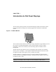
CHAPTER 1 Introduction to Flat Panel Displays The 3M Touch Systems product line of Flat Panel Display (FPD) touch monitors offers the M170 monitor for desktop and countertop applications with built-in multimedia options. Figure 1.
M170 FPD Monitor Installation Guide Capacitive and Resistive Options The monitor is available with 3M Touch System’s ClearTek® capacitive touch screen. Capacitive is the touch screen of choice for public access applications requiring high levels of durability and reliable performance 24 hours a day, 7 days a week. For those applications that require flexibility of input, including gloved hand use, we offer the M170 with a 5-wire resistive touch screen.
CHAPTER 2 Setting Up Your M170 FPD Monitor This chapter describes how to set up and integrate your 3M Touch Systems M170 FPD monitor into a touch application. You need to complete the following tasks: • Unpack the components • Connect the video, touch screen, and power cables to your computer • Power on the monitor and test your setup • Install the touch screen software • Calibrate the touch screen System Requirements The M170 flat panel touch monitor requires a personal computer (PC).
M170 FPD Monitor Installation Guide Unpacking Your Touch Monitor Carefully unpack the carton and inspect the contents. Your M170 monitor comes with most of these cables already connected.
Chapter 2 Setting Up Your M170 FPD Monitor 13 Figure 2. Removing the Base Cover Base Cover 65-2220 Tabs 1. Make sure the monitor is in its full upright position. 2. Push in and lift up on each of the two tabs located on the left and right sides of the base cover. This action will release the base cover. 3. Slide the cover back towards you to remove. Figure 3. Releasing the Cable Connector Cover Cable Connector Cover Press in tabs 65-2219 4.
M170 FPD Monitor Installation Guide Figure 4. Removing the Cable Connector Cover Keep tabs against LCD 65-2218 5. Lift this cover slightly so that the tabs are up against the rear of the LCD to keep them from catching on the cables below. Tilt the cover down as you slide the cover out from behind the support rods. Figure 5.
Chapter 2 Setting Up Your M170 FPD Monitor 15 Figure 6. Disassembling the LCD from Its Base for Arm Mounting Step 1 – Unlock front mechanism and disconnect all cables from the LCD. Step 2 -- With the unit laying face down safely and securely on a nonabrasive surface, remove the two screws connecting the name plate and support rods to the LCD. Lift the support rods out of the base and set aside. Step 3 -- Then remove the four screws holding the hinge in place and gently remove the base.
M170 FPD Monitor Installation Guide Countertop Base Mounting Option Keyhole slots in the bottom of the base plate enable you to secure the unit to a desktop or countertop. Use standard screws in the desktop or countertop and then slide the base plate on for a secure fit. Note: A full size template has been included in the back of this manual for your convenience. Simply tear out the template and drill directly through the holes indicated to secure your monitor to any surface.
Chapter 2 Setting Up Your M170 FPD Monitor 17 Figure 8. Adjusting the Viewing Angle Lift up latch to release lock and raise or lower display to suit your needs. Push down latch to engage lock and stabilize display position. Lift up on the latch to release lock. Adjust the M170 FPD by pushing or pulling on the top front of the monitor until the screen is at the best viewing angle for you. Then push down on latch to engage locking mechanism and stabilize display position.
M170 FPD Monitor Installation Guide Table 1.
Chapter 2 Setting Up Your M170 FPD Monitor 19 Multimedia Features The M170 FPD monitor comes with speakers built into the display bezel. The multimedia cable can be connected to the rear of the monitor for input. Figure 9. Multimedia Cable 6 Optional Card Reader Bracket The M170 FPD monitor is available with an optional card reader bracket (and (2) M3 screws) that supports IDTech and MagTech brand electronic card readers.
M170 FPD Monitor Installation Guide Table 2.
Chapter 2 Setting Up Your M170 FPD Monitor 4. 21 Plug the AC/DC power supply into the M170 FPD. Be sure to use the power supply included with the monitor. WARNING To avoid the risk of electric shock which could result in serious injury or death: • This device must be operated with the original power supply, part number: HJC, HASU05F.
M170 FPD Monitor Installation Guide Testing the M170 FPD Note: The M170 FPD has a power status LED located on the front of the bezel. After connection, turn on the power switch located on the front bezel. Before you test your touch monitor, make sure all cables are connected properly and routed through the cable management system. Be sure to tighten all cable screws. To test that the monitor is working properly: 1. Turn on your computer. 2. Make sure the video image is displayed.
Chapter 2 Setting Up Your M170 FPD Monitor 23 Calibrating the Touch Screen After you connect your touch monitor and install TouchWare™ software, you must calibrate the touch screen. Calibration serves two purposes: • Sets the active area of the touch screen • Aligns the touch screen’s active area to the underlying video To calibrate the touch screen, open the touch screen control panel and select Calibrate. Follow the directions displayed on the screen.
CHAPTER 3 Video Display Options This chapter provides guidelines for adjusting the video display and using the monitor controls to adjust the image to your liking. Before you make any adjustments: • Be sure to adjust the controls in your normal lighting conditions. • Display a test image or pattern whenever you adjust the video. Adjusting the M170 Video Display Your M170 FPD monitor has four main controls to adjust the video display.
M170 FPD Monitor Installation Guide If you do not press the Menu, Select, or ◄/left or ►/right adjust buttons for 45 seconds, the monitor adjustment program times out and hides the menu options. You can press the Menu button at any time to display the options again. Pressing MENU will pull up the On Screen Display (OSD) menu, as shown below. Figure 14.
Chapter 3 Video Display Options Icon 27 Description AUTO CONFIG If you change your display to Windows shut down mode, this adjustment will work better. Click on the "Start" button at the bottom right side, and then click Shut Down. This will bring you to the Windows shutdown mode. Then select Auto Adjust. The screen will adjust within 4 seconds. AUTO ADJUST Performs automatic configuration of the Phase, Clock, vertical, and horizontal position.
M170 FPD Monitor Installation Guide Icon Description OSD BLENDING: To adjust the brightness of the OSD MENU. LANGUAGE Selects a language among English, German, French, Spanish, Italian, Simplified Chinese or Traditional Chinese. CONTRAST Selecting the Contrast option increases (▲) or decreases (▼) the strength (lightness or dimness) of the image. Adjust the contrast using the ◄/left and ►/right arrow buttons, and press SELECT to confirm the new setting.
CHAPTER 4 Maintenance and Troubleshooting If you have a problem setting up or using your monitor, you may be able to solve it yourself. Before calling 3M Touch Systems, try the suggested actions that are appropriate to the problems you are experiencing with the monitor. You may also want to consult your video card user’s manual for additional troubleshooting advice.
M170 FPD Monitor Installation Guide • Apply the cleaner with a soft, lint-free cloth. Avoid using gritty cloths. • Always dampen the cloth and then clean the screen. Be sure to spray the cleaning liquid onto the cloth, not the screen, so that drips do not seep inside the display or stain the bezel. • Always handle the touch screen with care. Do not pull on or stress cables.
Chapter 4 Maintenance and Troubleshooting 31 Troubleshooting the Touch Screen If you are experiencing problems with the touch screen, check the following list of common installation errors. Table 3.
M170 FPD Monitor Installation Guide This equipment has been tested and found to comply within limits for a Class B digital device, pursuant to Part 15 of the FCC rules. These limits are designed to provide reasonable protection against harmful interference in residential installations. This equipment generates, uses and can radiate radio frequency energy, and if not installed and used in accordance with the instructions, may case harmful interference to radio communications.
M170 Base Plate Mounting Template ( Drawn actual size) 3M Touch Systems Proprietary Information Rear Edge of Base Not Shown Drill 4 Mounting Holes 0.178" (4.5 mm) Dia. 5.71" (145 mm) Place this template on mounting surface and drill four holes as shown for mounting screws. The screw heads must be smaller than 0.39" (10 mm) and larger than 0.21" (5.5 mm). Adjust height of screw heads to securely lock monitor in place. This height is about 0.178" (4.5 mm). 3.74" (95 mm) 0.39" (10 mm) 0.21" (5.