MP7640 Multimedia Projector Operator’s Guide MP7640 Projecteur multimédia Guide de l'opérateur MP7640 Multimedia-Projektor Benutzerhandbuch Proyector de Multimedia MP7640 Manual del Usuario MP7640 Proiettore Multimediale Manuale dell'operatore MP7640 Bruksanvisning för multimediaprojektor MP7640 Multimedia Projector Gebruiksaanwijzing © 3M IPC 2000 3M™ Multimedia Projector MP7640 1
3M™ Multimedia Projector MP7640 © 3M IPC 2000
Table of Contents Please click on any section to jump to that section. Introduction Safeguards .................................................................................... 4 Thank You for Choosing 3M .......................................................... 6 Warranty ........................................................................................ 6 Section 1: Unpack Contents of Shipping Box .............................................................. 7 Optional Accessories ............
Introduction Intended Use Before operating the machine, please read this entire manual thoroughly. The 3M™ Multimedia Projector MP7640 was designed, built, and tested for use indoors, using 3M lamps, 3M ceiling mount hardware, and nominal local voltages.
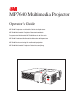
Introduction Location of Product Safety Labels The following safety labels are used on or within the MP7640 projector to alert you to items or areas requiring your attention. CAUTION/VORSICHT/MESURE DE PRÉCAUTION/ATTENZIONE/PRECAUCIÓN Turning the knob too much makes it come off. / Der Verstellknopf löst sich wenn er überdreht wird. / Si vous manipulez excessivament la poignée, elle se detachera. / Se si gira troppo la manipola si stacca. / Grandola demasiado la manivela se desprende.
Introduction Thank You for Choosing 3M Thank you for choosing 3M multimedia projection equipment. This product has been produced in accordance with 3M’s highest quality and safety standards to ensure smooth and troublefree use in the years to come. For optimum performance, please follow the operating instructions carefully. We hope you will enjoy using this high performance product in your meetings, presentations, and training sessions.
Section 1: Unpack Contents of Shipping Box The 3M™ MP7640 Multimedia Projector is shipped with the necessary cables required for standard VCR, PC, Macintosh™or laptop computer connections. Carefully unpack and verify that you have all of the items shown below. If any of these items are missing, please contact your place of purchase. STANDBY/ON VIDEO 0 MP764 t Safety Guide Produc RGB MP7640 Operator’s Guide ia Multimed MP7640 art Quick St MENU SELECT MENU POSITION RESET © 3M IPC July 2000 Rev.
Section 2: Product Description Machine Characteristics The MP7640 Multimedia Projector integrates ultra-high bright lamp and polysilicon LCD display technology into a single unit. It accepts input from one computer source and two video/audio sources, and projects a bright, super-crisp image. Switching your presentation from a computer input to a video input, then back to a computer input simply requires the push of a button on the remote control keypad or control panel keypad.
Section 2: Product Description Part Identification List 2 1 STANDBY/ON VIDEO RGB MENU SELECT MENU MAGNIFY POSITION FREEZE RESET VOLUME MUTE AUTO TIMER 3 BLANK 4 12 15 14 11 10 9 5 8 7 6 13 Figure 2.1 Identifying MP7640 Parts 1. Basic remote control transmitter 2. Control panel keypad (see below) a) STANDBY/ON button b) ON, LAMP, TEMP indicators c) INPUT, MUTE, RESET buttons d) MENU disk button 3. Stereo Speaker 4. Air filter cover 5. Height adjustment foot lock button 6.
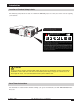
Section 2: Product Description System Setup—Connecting to Various Equipment AC Power VCR with S jack Laptop Computer Desktop Computer VCR Figure 2.2 Cable Connections Turn power off to all devices before making connections. Never plug anything into the projector or computer while any device is in operation. Caution 10 The MP7640 must be powered down when making connections. The mouse emulation may not work if the unit is not powered down before the mouse cable connections are made.
Section 2: Product Description Remote Control Transmitter Identification STANDBY/ON STANDBY/ON VIDEO RGB Turn on Main Power switch. Press STANDBY/ON button to begin projection mode (lamp on) or press and hold button for one second to switch to standby mode (lamp off). VIDEO and RGB Press the VIDEO or RGB button to select the input source. Press again to select the next source. MENU SELECT Press to select menu items.
Section 2: Product Description Changing Remote Control Battery Caution This battery contains lithium. Consult your local hazardous waste regulations and dispose of this battery in the proper manner. This remote control transmitter uses a lithium battery located in a sliding holder inserted into the bottom of the transmitter. 1. Turn the remote control transmitter over to access the battery holder. 2. Push the smaller tab inward as indicated below. 3.
Section 3: Basic Operations Projector Start-up STANDBY/ON INPUT MUT Figure 3.1 Projector Controls 1. Make all equipment and cable connections with the power off. 2. Turn on the MAIN POWER SWITCH 3. Press the STANDBY/ON button . The ON indicator will blink green during warm-up and lamp ignition, then stay green to indicate correct operation. When power is turned off, there is a 60-second reset period before the STANDBY/ON button will function again. 4. Turn on all connected equipment.
Section 4: Adjustments and Functions How to Use Height Adjustment Foot Adjust the image elevation and projection angle (within 0 to 10°) using the height adjustment foot at the front of the projector. 1. 2. 3. 4. 5. Raise the front end of the projector so the foot is not touching the tabletop. Push the lock button on the left side of the projector to unlock the foot. Extend or retract the foot to the desired height. Release the lock button to lock the foot into position.
Section 4: Adjustments and Functions Plug & Play Function Plug & Play is a system configured with peripheral equipment (including a computer and display), and a compatible operating system. This allows the user to connect various peripheral equipment successfully without having to adjust settings manually. The equipment and projector exchange this information automatically. This projector is VESA DDC (Display Data Channel) 1/2B compatible.
Section 4: Adjustments and Functions Menu Navigation MENU SELECT Figure 4.3 Menu disk button on projector and Menu buttons from basic remote control transmitter 1. Press MENU disk button on projector or remote control MENU buttons. On-screen menus are displayed on the projected image. 2. Select the menu to be adjusted using the MENU disk button or remote control Menu buttons Selected Menu is then highlighted. . 3.
Section 4: Adjustments and Functions SETUP Submenu The SETUP sub-menu is used to adjust and move the image position. The projector will display either the RGB (Figure 4.5) or Video (Figure 4.6) submenu, according to the input source being projected. SETUP INPUT IMAGE OPT. SETUP INPUT BRIGHT BRIGHT CONTRAST CONTRAST V POSIT SHARPNESS H POSIT 121 H PHASE 57 TINT H SIZE COLOR BAL R 800 COLOR BAL R OPT. COLOR 7 H SIZE IMAGE COLOR BAL B COLOR BAL B ASPECT Figure 4.
Section 4: Adjustments and Functions INPUT Submenu The INPUT submenu is used to select the RGB or video input source. The RGB values are shown in Figure 4.7. The Video values are shown in Figure 4.8. SETUP INPUT RGB IMAGE FH: 48.3 VIDEO FV: 60 OPT. SETUP KHz INPUT IMAGE OPT. RGB Hz AUTO VIDEO AUTO NTSC AUTO PAL SECAM NTSC4.43 M-PAL N-PAL Figure 4.7 RGB Input Submenu SETUP Figure 4.8 Video Input Submenu INPUT IMAGE OPT. RGB VIDEO AUTO EXECUTE CANCEL Figure 4.
Section 4: Adjustments and Functions IMAGE Submenu The IMAGE submenu is used to change the image characteristics. SETUP INPUT IMAGE KEYSTONE BLANK MIRROR START UP SETUP KEYSTONE BLANK MIRROR START UP OPT. ±0 INPUT IMAGE NORMAL H: INVERT V: INVERT H&V: INVERT OPT. SETUP INPUT IMAGE OPT. INPUT IMAGE OPT. KEYSTONE BLANK MIRROR START UP SETUP KEYSTONE BLANK MIRROR START UP TURN ON TURN OFF Figure 4.
Section 4: Adjustments and Functions OPT. Submenu The OPT. submenu allows you to control communication function. SETUP INPUT IMAGE OPT. SETUP 8 VOLUME MENU COLOR TIMER LANGUAGE AUTO OFF AUTO OFF SYNC ON G SYNC ON G IMAGE OPT. SETUP INPUT VOLUME VOLUME MENU COLOR MENU COLOR TIMER TIMER 15 min. LANGUAGE OPT. IMAGE OPT.
Section 5: Maintenance Cleaning the Air Filter ✔ Note: Clean the air filter about every 50 hours or if the message “CHECK AIR FLOW” is displayed on the screen. If air is restricted due to dust accumulation on filter, the projector may overheat and shut down automatically. Turn off the MAIN POWER SWITCH of the projector and pull out power cord. Let cool for 20 minutes. Vacuum dust and dirt from filter. Figure 5.
Section 6: Lamp Lamp The following symptoms may indicate that the lamp needs to be replaced: • LAMP indicator lights up red. • “CHANGE THE LAMP” message appears on the screen. Display Lamp Operation Hours To determine the lamp operation hours: 1. While the projector is running, press and hold the TIMER button on the remote control for three seconds. 2. The operating time of the lamp will be displayed at the bottom of the screen.
Section 6: Lamp Replacing the Lamp WARNING WARNING To reduce the risk of electrical shock, always turn off projector and disconnect power cord before changing lamp. ✔ Note: For maximum lamp life, do not shock, handle or scratch the lamp glass when it is hot. Do not use an old or previously used lamp as a replacement lamp. 1. Remove lamp access door: The lamp access door is located on the bottom of the machine.
Section 7: Troubleshooting Symptoms/Solutions Symptom Cause Solution Power cannot be turned on. • MAIN POWER switch is not turned on. • Turn the MAIN POWER switch on. • The power cord is disconnected. • Insert the power cord into an AC socket. • 60 seconds have not elapsed since • Wait 60 seconds before turning on power. the power was turned off. No picture or sound. • The setting of the input source is not • Set the correct input using the input select button of correct.
Section 7: Troubleshooting Indicator Lights POWER Indicator Light LAMP Indicator Light TEMP Indicator Light Lights orange Turns off Turns off Standby status Blinks green Turns off Turns off Warming up. Wait. Lights green. Turns off. Turns off. Operation status. Blinks orange. Turns off. Turns off. Cool down. Turns off. The lamp does not light. Wait approx. 20 minutes before turning on power again. If indicator still lights, the lamp may have failed. Replace lamp. Turns off.
Section 7: Troubleshooting Service Information For product information, product assistance, service information, or to order accessories, please call: • In U.S. or Canada: 1-800-328-1371 • In other locations, contact your local 3M sales office.
Important Notice All statements, technical information, and recommendations related to 3M’s products are based on information believed to be reliable, but the accuracy or completeness is not guaranteed. Before using this product, you must evaluate it and determine if it is suitable for your intended application. You assume all risks and liability associated with such use.