DATASHEET DIABLO16 Processor Embedded Graphics Processor Document Date: 22nd April 2014 Document Revision: 1.4 Uncontrolled Copy when printed or downloaded.
DIABLO16 PROCESSOR Contents 1. Description ............................................................................................................................. 4 2. Features ................................................................................................................................. 4 3. Applications ........................................................................................................................... 5 4. Pin Summary .......................................
DIABLO16 PROCESSOR 12.1. Workshop 4 – Designer Environment ................................................................................................ 27 12.2. Workshop 4 – ViSi Environment......................................................................................................... 27 12.3. Workshop 4 – ViSi Genie Environment .............................................................................................. 27 12.4. Workshop 4 – Serial Environment...............................
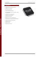
DIABLO16 PROCESSOR 4D SYSTEMS DIABLO16 Processor 1. Description 2. Features The DIABLO16 Processor is the latest addition to the 4D Systems processor range, providing more power, more FLASH, more RAM and more features than the PICASO Processor. • 6 banks of 32750 bytes of Flash memory for User Application Code and Data The DIABLO16 Processor is a custom embedded 4DGL graphics controller designed to interface with many popular OLED and LCD display panels.
DIABLO16 PROCESSOR 4D SYSTEMS DIABLO16 Processor 3. Applications • General purposes embedded graphics. • Elevator control systems. • Point of sale terminals. • Electronic gauges and metres. • Test and measurement and general purpose instrumentation. • Industrial control and Robotics. • Automotive system displays. • GPS navigation systems. • Medical Instruments and applications. • Home appliances and Smart Home Automation. • Security and Access control systems. • Gaming equipment. • Aviation systems.
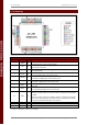
DIABLO16 PROCESSOR 4D SYSTEMS DIABLO16 Processor 4. Pin Summary DIABLO16 Processor Pin Out I/O Description Pin Symbol 1 AUDIO O 2 XR A 3 YU A 4 SD-SCK O 5 SD-SDI I 6 SD-SDO O 7 RESET I 8 SD-CS O 19 AVCC P 20 9, 25, 34, 41 10, 26, 38, 57 AGND GND VCC P P P Pulse Width Modulated (PWM) Audio output. Connect this pin to a 2 stage low pass filter then into an audio amplifier. 4-Wire Resistive Touch Screen Right signal. Connect this pin to XR or X+ signal of the touch panel.
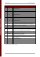
DIABLO16 PROCESSOR 4D SYSTEMS DIABLO16 Processor DIABLO16 Processor Pin Out (continued…) I/O Description Pin Symbol 11 12 13 14 15 16 17 18 21 22 23 24 27 28 29 30 31 32 D5 D4 D3 D2 D1 D0 D6 D7 D8 D9 D10 D11 D12 D13 D14 D15 PA12 PA13 I/O I/O I/O I/O I/O I/O I/O I/O I/O I/O I/O I/O I/O I/O I/O I/O I I 33 TX0 O 36 37 39 40 PA15 PA14 CLK1 CLK2 I/O I/O I O 42 RX0 I 43 44 PA10 PA11 I/O I/O 45 AUDIOENB O 46 PA4 I/O 47 XL O 48 YD O 49 50 51 52 53 PA5 PA6 PA7 PA8 PA9 I/O I/O I/O I
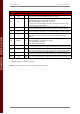
DIABLO16 PROCESSOR 4D SYSTEMS DIABLO16 Processor DIABLO16 Processor Pin Out (continued…) I/O Description Pin Symbol 54 RES O 55 RS O 56 REF P 58 WR O 59 RD O 60 DCENB O 61 PA0 I/O/A 62 PA1 I/O/A 63 PA2 I/O/A 64 PA3 I/O/A Display RESET. DIABLO16 initialises the display by strobing this pin LOW. Connect this pin to the Reset (RES) signal of the display. Display Register Select. LOW: Display index or status register is selected.
DIABLO16 PROCESSOR 4D SYSTEMS DIABLO16 Processor 5. Pin Description The DIABLO16 Processor provides both a hardware and a software interface. This section describes in detail the hardware interface pins of the device. 5.1. Display Interface The DIABLO16 supports LCD and OLED displays with an 80-Series 16-bit wide CPU data interface. The connectivity to the display is easy and straight forward. The DIABLO16 generates all of the necessary timing to drive the display.
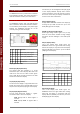
DIABLO16 PROCESSOR 4D SYSTEMS DIABLO16 Processor 5.2. SPI Interface – Memory Card Item Sym Min Typ Max Unit Read Low Pulse tRL 150 - - ns Read High Pulse tRH 150 - - ns Read Bus Cycle Total tRT 300 - - ns Read Data Hold tDH 75 - - ns The DIABLO16 supports SD, micro-SD and MMC memory cards via its dedicated hardware SPI interface. The DIABLO16 has 4 SPI channels, and the first is dedicated for this.
DIABLO16 PROCESSOR 4D SYSTEMS DIABLO16 Processor 5.3. Serial Ports – TTL Level Serial The DIABLO16 Processor has three hardware asynchronous serial ports that can be configured on a variety of the processors GPIO pins. TX/RX0 is dedicated and is fixed on to pins 33 (TX0) and 43 (RX0). All of the DIABLO16’s serial ports can be used to communicate with external serial devices. TX/RX0 are referred to as COM0, and is the only one used for programming the DIABLO16 itself.
DIABLO16 PROCESSOR 4D SYSTEMS DIABLO16 Processor 5.5. Touch Screen Interface DIABLO16 Serial TTL Comm Port Configuration Options TX1 PA0 PA1 PA2 PA3 PA4 PA5 PA6 PA7 PA8 PA9 PA10 PA11 PA12 PA13 PA14 PA15 ✓ ✓ ✓ ✓ ✓ ✓ ✓ ✓ ✓ ✓ RX1 ✓ ✓ ✓ ✓ ✓ ✓ ✓ ✓ ✓ ✓ ✓ ✓ ✓ ✓ TX2 ✓ ✓ ✓ ✓ ✓ ✓ ✓ ✓ ✓ ✓ RX2 ✓ ✓ ✓ ✓ ✓ ✓ ✓ ✓ ✓ ✓ ✓ ✓ ✓ ✓ TX3 ✓ ✓ ✓ ✓ ✓ ✓ ✓ ✓ ✓ ✓ RX3 ✓ ✓ ✓ ✓ ✓ ✓ ✓ ✓ ✓ ✓ ✓ ✓ ✓ ✓ Please refer to the 'DIABLO16-4DGL-InternalFunctions.pdf' document for information on how to set the DIABLO16 pin mappings. 5.4.
DIABLO16 Processor source/sink 10mA. For more information see Chapter 16, ‘Specifications and Ratings’. 5.6. GPIO - General Purpose IO There are 16 general purpose Input/Output (GPIO) pins available to the user. These provide flexibility of individual bit operations along with serving collectively for byte wise operations using the BUS functions ✓ ✓ ✓ ✓ ✓ ✓ ✓ ✓ ✓ ✓ ✓ ✓ ✓ ✓ ✓ ✓ ✓ ✓ ✓ ✓ ✓ ✓ ✓ ✓ ✓ ✓ ✓ ✓ ✓ ✓ PA14-PA15: Input only pins. These pins can only be Digital Inputs. Note: All GPIO pins are 5.
DIABLO16 Processor RESET pin (Device Master Reset): Device Master Reset pin. An active low pulse of greater than 2 micro-seconds will reset the device. Connect a resistor (1K to 10K, nominal 4.7K) from this pin to VCC. Only use open collector type circuits to reset the device if an external reset is required. This pin is not driven low by any internal conditions.
DIABLO16 Processor The following table illustrates which of the GPIO 2 can be used for the three different I C channels available. 2 I C2 SDA 2 I C2 SCL 2 I C3 SDA 2 2 ✓ ✓ ✓ ✓ ✓ ✓ ✓ ✓ ✓ ✓ ✓ ✓ ✓ ✓ ✓ ✓ ✓ ✓ ✓ ✓ ✓ ✓ ✓ ✓ ✓ ✓ ✓ ✓ ✓ ✓ ✓ ✓ ✓ ✓ ✓ ✓ ✓ ✓ ✓ ✓ ✓ ✓ ✓ ✓ ✓ ✓ ✓ ✓ ✓ ✓ ✓ ✓ ✓ ✓ ✓ ✓ ✓ ✓ ✓ ✓ ✓ ✓ ✓ ✓ ✓ ✓ ✓ ✓ ✓ ✓ ✓ ✓ ✓ ✓ ✓ ✓ ✓ ✓ ✓ ✓ ✓ ✓ ✓ ✓ SPECIAL SPECIAL SPECIAL SPECIAL SPECIAL – please see Section 5.
DIABLO16 PROCESSOR 4D SYSTEMS DIABLO16 Processor 5.10. I2C 5.11. Pulse Out 2 There are 3 user configurable I C channels available for mapping to GPIO, for use by the user 2 for the target application. All 3 I C channels are Master only, and cannot be configured to be slaves at this time. Please refer to the table on the previous page for 2 details on which GPIO can be configured for I C.
DIABLO16 PROCESSOR 4D SYSTEMS DIABLO16 Processor 5.12. PWM Out 5.13. Pin Counter There are 6 PWM channels available to be configured by the user, with 4 time bases available for selection. There are 6 Pin Counter channels available to be configured by the user, used to count incoming pulses with the ability to call a user function on overflow. The Pin Counter function is available for use in a variety of modes. The PWM can be configured to be used in Servo Mode, or Simple Mode.
DIABLO16 PROCESSOR 4D SYSTEMS DIABLO16 Processor 5.14. Quadrature In 5.15. Analog Inputs There are two Quadrature Input channels available on the DIABLO16 processor, which requires 2 GPIO pins each. Please refer to the table in section 5.6 for details on which GPIO can be configured to be analog inputs. Please refer to the table on the previous page for details on which GPIO can be configured for Quadrature Input.
DIABLO16 PROCESSOR 4D SYSTEMS DIABLO16 Processor for the 4 channels, and ‘func’ is the user function to call when the number of samples specified have been collected. Example Connection Diagram This illustrates an analog input being configured on GPIO PA1, and is used to read an analog temperature from a temperature sensor. 6. DIABLO16 Architecture The figure below illustrates the DIABLO16 Processors architecture.
DIABLO16 PROCESSOR 4D SYSTEMS DIABLO16 Processor to include libraries, or wait for hefty compile times – it’s all built in. 6.1. FLASH Storage and RAM allocation The figure below illustrates how the FLASH and RAM are allocated in the System, and what is available for use by the system and by the user. Each area is explained in the sections following. The PmmC is in protected memory, and cannot be read or damaged by inadvertent writes to illegal FLASH areas.
DIABLO16 PROCESSOR 4D SYSTEMS DIABLO16 Processor flash_Copy() flash_WriteBlock() 6.5. RAM (Both System and User) An application in one bank can store applications from microSD card and writing them to a bank for future execution using the 4DGL function flash_LoadFile() An application in one bank can read data stored in another bank, such as graphics or strings stored there, and retrieve them and display them as required.
DIABLO16 PROCESSOR 4D SYSTEMS DIABLO16 Processor 7. 4DGL - Software Language 8. In Circuit Serial Programming ICSP The DIABLO16 processor belongs to a family of processors powered by a highly optimised soft core virtual engine, EVE (Extensible Virtual Engine). The DIABLO16 processor is a custom graphics processor. All functionality including the high level commands are built into the chip.
DIABLO16 PROCESSOR 4D SYSTEMS DIABLO16 Processor 9. System Registers Memory Map The following tables outline in detail the DIABLO16 system registers and flags.
DIABLO16 PROCESSOR 4D SYSTEMS LABEL DIABLO16 Processor DIABLO16 System Registers and Flags (continued…) ADDRESS USAGE DEC HEX MEDIA_SECTOR_HI 93 0x5D micro-SD sector address HI MEDIA_SECTOR_COUNT 94 0x5E micro-SD number of bytes remaining in sector TEXT_XPOS 95 0x5F text current x pixel position TEXT_YPOS 96 0x60 text current y pixel position TEXT_MARGIN 97 0x61 text left pixel pos for carriage return TXT_FONT_ID 98 0x62 font type, 0 = system font, else pointer to user font TXT_FONT_MAX 99 0x63 max numb
DIABLO16 PROCESSOR 4D SYSTEMS DIABLO16 Processor 10. Memory Cards - FAT16 Format 11. Hardware Tools The DIABLO16 Processor uses off the shelf standard SDHC/SD/micro-SD memory cards with up to 2GB capacity usable with FAT16 formatting. For any FAT file related operations, before the memory card can be used it must first be formatted with FAT16 option. The formatting of the card can be done on any PC system with a card reader.
DIABLO16 PROCESSOR 4D SYSTEMS DIABLO16 Processor 11.2. Evaluation Display Modules 12. 4D Systems - Workshop 4 IDE 4D Systems has a number of modules available which can be used for evaluation purposes or equally as final products, to discover what the DIABLO16 processor has to offer. Workshop4 is a comprehensive software IDE that provides an integrated software development platform for all of the 4D family of processors and modules.
DIABLO16 PROCESSOR 4D SYSTEMS DIABLO16 Processor 12.1. Workshop 4 – Designer Environment 12.3. Workshop 4 – ViSi Genie Environment Choose the Designer environment to write 4DGL code in its raw form. ViSi Genie is a breakthrough in the way 4D Systems’ graphic display modules are programmed. It is an environment like no other, a code-less programming environment that provides the user with a rapid visual experience, enabling a simple GUI application to be ‘written’ from scratch in literally seconds.
4D SYSTEMS DIABLO16 Processor simple graphic commands can be sent from the users host microcontroller to display primitives, images, sound or even video. Refer to the “Serial Command Set Reference Manual” from the Workshop 4 product page on the 4D Systems website for a complete listing of all the supported serial commands DIABLO16 PROCESSOR By default, each module shipped from the 4D Systems factory will come pre-programmed ready for use in the Serial mode. © 2014 4D SYSTEMS Page 28 of 33 www.
4D SYSTEMS DIABLO16 Processor DIABLO16 PROCESSOR 13. Reference Design © 2014 4D SYSTEMS Page 29 of 33 www.4dsystems.com.
4D SYSTEMS DIABLO16 Processor DIABLO16 PROCESSOR 14. Package Details © 2014 4D SYSTEMS Page 30 of 33 www.4dsystems.com.
4D SYSTEMS DIABLO16 Processor DIABLO16 PROCESSOR 15. PCB Land Pattern © 2014 4D SYSTEMS Page 31 of 33 www.4dsystems.com.
DIABLO16 PROCESSOR 4D SYSTEMS DIABLO16 Processor 16. Specifications and Ratings ABSOLUTE MAXIMUM RATINGS Operating ambient temperature ................................................................................................... -40°C to +85°C Storage temperature ........................................................................................................................ -65°C +150°C Voltage on VCC with respect to GND ......................................................................
DIABLO16 PROCESSOR 4D SYSTEMS DIABLO16 Processor 17. Legal Notice Proprietary Information The information contained in this document is the property of 4D Systems Pty. Ltd. and may be the subject of patents pending or granted, and must not be copied or disclosed without prior written permission. 4D Systems endeavours to ensure that the information in this document is correct and fairly stated but does not accept liability for any error or omission.