
Datasheet


4D SYSTEMS DIABLO16 Processor
© 2014 4D SYSTEMS Page 6 of 33 www.4dsystems.com.au
DIABLO16 PROCESSOR
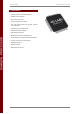
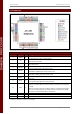
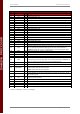
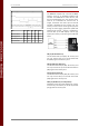
4. Pin Summary
DIABLO16 Processor Pin Out
Pin
Symbol
I/O
Description
1
AUDIO
O
Pulse Width Modulated (PWM) Audio output. Connect this pin to a 2 stage
low pass filter then into an audio amplifier.
2
XR
A
4-Wire Resistive Touch Screen Right signal. Connect this pin to XR or X+
signal of the touch panel.
3
YU
A
4-Wire Resistive Touch Screen Up signal. Connect this pin to YU or Y+ signal
of the touch panel.
4
SD-SCK
O
SPI Serial Clock output. SD memory card use only. Connect this pin to the SPI
Serial Clock (SCK) signal of the memory card.
5
SD-SDI
I
SPI Serial Data Input. SD memory card use only. Connect this pin to the SPI
Serial Data Out (SDO) signal of the memory card.
6
SD-SDO
O
SPI Serial Data Output. SD memory card use only. Connect this pin to the SPI
Serial Data In (SDI) signal of the memory card.
7
RESET
I
Master Reset signal. Connect a 4.7K pull-up resistor from this pin to VCC.
Active Low
8
SD-CS
O
SD Memory-Card Chip Select. SD memory card use only. Connect this pin to
the Chip Enable (CS) signal of the memory card.
19
AVCC
P
Analog Positive Supply.
Option 1: Connect to VCC via a 12ohm resistor, and with a 4.7uF Capacitor
to AGND
Option 2: Connect to VCC via an Inductor with has a resistance of less than
1ohm, and a capacity greater than 10mA, and a 4.7uF Capacitor to AGND.
This option provides the best ADC noise rejection.
20
AGND
P
Analog Ground. Connect this to GND.
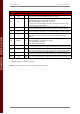
9, 25, 34, 41
GND
P
Device Ground.
10, 26, 38, 57
VCC
P
Device Positive Supply.
I = Input, O = Output, P = Power, A = Analogue