
Datasheet


4D SYSTEMS DIABLO16 Processor
© 2014 4D SYSTEMS Page 8 of 33 www.4dsystems.com.au
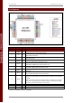
DIABLO16 PROCESSOR
I = Input, O = Output, P = Power, A = Analogue
NOTE: Please refer to section 5 for more information about these pins.
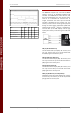
DIABLO16 Processor Pin Out (continued…)
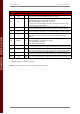
Pin
Symbol
I/O
Description
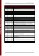
54
RES
O
Display RESET. DIABLO16 initialises the display by strobing this pin LOW.
Connect this pin to the Reset (RES) signal of the display.
55
RS
O
Display Register Select.
LOW: Display index or status register is selected.
HIGH: Display GRAM or register data is selected.
Connect this pin to the Register Select (RS or A0 or C/D or similar naming
convention) signal of the display.
56
REF
P
Internal voltage regulator filter capacitor pin. Connect a 4.7uF to 10uF
capacitor from this pin to Ground. Position capacitor as close as possible.
58
WR
O
Display Write strobe signal. DIABLO16 asserts this signal LOW when writing
data to the display. Connect this pin to the Write (WR) signal of the display.
59
RD
O
Display Read strobe signal. DIABLO16 asserts this signal LOW when reading
data from the display. Connect this pin to the Read (RD) signal of the
display.
60
DCENB
O
DC-DC high voltage enable signal. This maybe the high voltage that drives
the LCD backlight or the OLED panel supply.
High: Enable DC-DC converter.
Low : Disable DC-DC converter.
61
PA0
I/O/A
General Purpose I/O pin with Analog Capability. This pin is 5.0V tolerant
when used as a Digital, with a range of 0-3.3V when used as an Analog Input
62
PA1
I/O/A
General Purpose I/O pin with Analog Capability. This pin is 5.0V tolerant
when used as a Digital, with a range of 0-3.3V when used as an Analog Input
63
PA2
I/O/A
General Purpose I/O pin with Analog Capability. This pin is 5.0V tolerant
when used as a Digital, with a range of 0-3.3V when used as an Analog Input
64
PA3
I/O/A
General Purpose I/O pin with Analog Capability. This pin is 5.0V tolerant
when used as a Digital, with a range of 0-3.3V when used as an Analog Input