Weighing Indicator WM+PD4000508
This manual and Marks All safety messages are identified by the following, “WARNING” or “CAUTION”, of ANSI Z535.4 (American National Standard Institute: Product Safety Signs and Labels). The meanings are as follows: WARNING CAUTION A potentially hazardous situation which, if not avoided, could result in death or serious injury. A potentially hazardous situation which, if not avoided, may result in minor or moderate injury. This is a hazard alert mark.
Contents 1. Compliance.................................................................................................................. 3 1.1.1. Compliance with FCC Rules.......................................................................... 3 1.1.2. Compliance with European Directives ........................................................... 3 2. Introduction .................................................................................................................. 4 3.
9.1.1. Using Code Memory .................................................................................... 35 10. Comparison................................................................................................................ 36 10.1. Weight Check Mode............................................................................................ 36 10.1.1. Condition Formula for Comparison .............................................................. 37 10.1.2.
1. Compliance 1.1.1. Compliance with FCC Rules Please note that this equipment generates, uses and can radiate radio frequency energy. This equipment has been tested and has been found to comply with the limits of a Class A computing device pursuant to Subpart J of Part 15 of FCC rules. These rules are designed to provide reasonable protection against interference when this equipment is operated in a commercial environment.
2. Introduction The AD-4407 is a weighing indicator that amplifies signals from a load cell, converts it to digital data and displays it as a mass value. This indicator has the following performance: Input sensitivity: ......................... 0.25 mV /division. Maximum display: ...................... 40000 divisions. Refresh rate of the display: ........ 10 times/second approximately. Input voltage range: ................... -1 mV ~ +15 mV.
3. Installation and Precautions 3.1.1. Installation and Precautions The weighing indicator is a precision electronic instrument. Handle it carefully. The operating temperature is -10°C to +40°C (14°F to 104°F). Do not install the scale in direct sunlight. Mis-operation or other problems may be caused by an unstable power source including momentary power failure or instantaneous noise. Use a stable power source. Do not connect the power cord before the installation has been completed.
3.1.3. Caution Adjustment of the Load Cell Output Use a metal film resistor in the range of 50kohm to 500kohm with a good temperature coefficient, when adding a resistor to adjust a load cell output. Use as large of a resistance value as possible in the range in which the zero adjustment is possible. Solder this resistor at a point near the load cell or the indicator. In Case of Reducing the Output Voltage When the zero output is too large, add a resistor between EXC+ and SIG-.
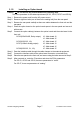
3.1.5. Installing an Option board Caution Do not remove any screws without the following step. This is the procedure for the data output board (OP-03, OP-05, OP-07 and OP-08). Step 1 Remove the power cord from the AC power source. Step 2 Remove eight hex bolts (one of them is the sealing bolt) from the rear panel. Step 3 Remove the rear panel carefully as there are cables between the front unit and the rear panel.
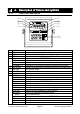
4. Description of Panels and symbols 4.1.1. Front Panel Description TOTAL PRINT No. Name 1 STABLE 2 NET 3 ZERO PT READY 4 M+ (Accumulation) Triangle 1,2,3 5 Main display 6 UNIT part 7 HI/OK/LO 8 Capacity label 9 CODE key SAMPLE key SETPOINT key PT key TOTAL key M+ key START key STOP key MODE key 0 – 9 key A – F key ZERO key CLEAR key TARE key Description Indicates when the display is stable. Indicates when the weight is net weight.
9 ESC key NET/GROSS key +/- key ENTER key PRINT key ON/OFF key 4.1.2. The key to proceed to the next step without changing the data. The key to select net or gross weight in the display. The key to select the sign of a value. The key to confirm parameters and stores the data. The key to output data (press quickly). The key to turn the indicator on and off (OFF: hold for 3 seconds). Rear Panel Description 10 12 13 14 15 11 No.
4.1.3. Other Displays and Symbols Standby display. Zero error when turning the display on. If the ESC key is pressed, the current weighing value may be displayed. Over load display. Remove any load from the load cell immediately. It may cause damage to the load cell(s). Example of an error display. 4.1.4.
5. Calibration This indicator, converts an input voltage from a load cell to the "mass" value, and displays it. Calibration is the adjustment function so that the scale (indicator) can display the weight correctly. 5.1.1. Items of Calibration Mode There are four items in the calibration function in the procedure. How to calibrate: In weighing mode, press the CAL key. After Cal in is displayed for 2 seconds Cal 0 will appear.
Note that the ON/OFF key does not function alone. Press the ESC key while holding the ON/OFF key to end the calibration mode, if mis-operation. After displaying Can5el, press the ON/OFF key to stop calibration mode and to turn the indicator off. NOTE: When displaying Caloff , press the +/- key while pressing the ON/OFF key, instead of CAL key. Caution The maximum display is less than or equal to 40000 divisions. This number is calculated from the maximum capacity divided by the minimum division.
Single Range Select resolution and decimal point position and format. Specify the weighing capacity. Dual Range Select the resolution, decimal point position and format. Select the weighing range Select the resolution Specify the weighing capacity For the range function, refer to “5.3. Weighing Range Function”. Specifying the Range and Unit Step 1 The range and unit of measure are displayed.
Specifying the Weighing Range of the First Range Step 3 After displaying Cap for 2 seconds, single range or the weighing capacity will be displayed. When dual range is used, Cap1 is displayed for 2 seconds. Triangle 1 will be displayed. Specify data with the 0 - 9 keys and press the ENTER key to store it and proceed to the next step. When pressing the ESC key, regardless of what is displayed, the indicator will proceed to the next step without changing it.
5.2.3. Zero Calibration Procedure Step 8 Check the Cal 0 display. Select a zero calibration method to adjust the zero point The adjustment method Weighing input with nothing on the To step 9 (Normal way) weighing unit. The numerical way to Digital input input a load cell output To step 10 voltage. Zero calibration Place nothing on the weighing unit (No load) Weighing Input Step 9 Place nothing on the weighing unit. Press the ENTER Turn on STABLE mark key after the STABLE mark has turned ON.
Weighing a Mass except the Maximum Capacity Step12 Specify a mass value using 0 - 9 keys. Span calibration Step13 Place a mass equivalent to displayed value on the weighing unit. Proceed to step 15. Maximum capacity To step 14, step 16 To step 12 Weighing Capacity Mass Step14 Place a mass equivalent to the maximum capacity on the weighing unit. 0 Step15 Press the ENTER key after the STABLE New mass value mark turns on. Proceed to step 17. ESC key ..........
ESC key ..... The key to store the parameters temporarily. Proceed to the Cal 0 display. Press and hold the ON/OFFkey and press the ESC key No parameters are changed, CanCel is displayed and the calibration mode is finished. Step18 Press the ON/OFF key to turn the display off. 5.3. Weighing Range Function The weighing range function can select "single range" and "dual range". Specify each weighing interval (division) for the multi-interval instrument.
5.3.1. Selecting the Division and Range Consider the following rules to design the weighing range. Rule 1 Select the division and range of each weighing range so as to fit the following inequality. The first range < the second range The division of the next weighing range is automatically set larger than the division of the lower weighing range. And the division can change. Rule 2 When specifying the dual range, the upper limit value of the second range becomes the maximum capacity.
5.5. Gravity C Compensation ompensation Function If the scale is used at the calibration location, it is not necessary to perform this function. If there is a difference of gravity acceleration between the installed location and calibration location it may cause a weighing error. This function specifies the gravity acceleration and corrects the span error. Note The decimal point is not displayed in the function. Example: 9798 = 9.
5.5.1. The Gravity Acceleration Table Amsterdam Athens Auckland NZ Bangkok Birmingham Brussels Buenos Aires Calcutta Chicago Copenhagen Cyprus Djakarta Frankfurt Glasgow Havana Helsinki Kuwait Lisbon London (Greenwich) Los Angeles Madrid 5.5. Gravity Compensation Function 9.813 9.800 9.799 9.783 9.813 9.811 9.797 9.788 9.803 9.815 9.797 9.781 9.810 9.816 9.788 9.819 9.793 9.801 9.812 9.796 9.
5.6. Calibration Error Code List Exiting from a calibration error ESC key ..... The key to return the point where an error occurred. Retry the operation. ESC key while pressing the ON/OFF key. No parameters are changed, CAnCEL is displayed and the calibration mode is finished. Press ON/OFF key to turn the display off. Error Code List If an error has occurred during the calibration mode, the following code is displayed.
6. Functions There are two parameters lists, one for the F-functions and one for the CF-functions. These functions control the indicator. The parameters of each function are stored in the non-volatile memory, and are not lost even if power is turned off or cut off. F-functions: These parameters can always be changed and are used for internal settings. CF-functions: If you accept a certificated approval of the weighing instruments, the CAL cover (rear panel) must be sealed.
6.2. F-Functions Weighing Conditions (Digital Filter, Zero trucking and Stability) Item Parameter Description 2 d/ 1.6s 0 4 d/ 1.6s 1 8 d/ 1.6s 2 16 d/ 1.6s 3 32 d/ 1.6s 4 64 d/ 1.6s 5 If weak filter is set, the response f00 Filter will be fast, but will be more 128 d/ 1.6s 6 Motion / Averaging sensitive to external influences 2 d/ 3.2s 7 time such as vibration. **8 4 d/ 3.2s 8 d/ 3.2s 9 16 d/ 3.2s 10 32 d/ 3.2s 11 64 d/ 3.2s 12 128 d/ 3.2s 13 OFF 0 This function traces the weight 0.
Display and Other General Functions Item Parameter *0 5 times/s f04 Display update rate 10 times/s 1 1x Key click (ON/OFF) 2x LoLo / Zero band 3x Lo f05 [Type2] 4x OK Buzzer 5x HI 6x 00 to f06 Device ID(Address) 99 *0 f07 Counting function 1 *: Initial settings. s: Key Switch Item f12 [Type2] Disabling of key switch *: Parameter 10 11 20 21 30 31 40 41 50 51 60 61 70 71 80 81 90 91 a0 a1 b0 b1 C0 C1 d0 d1 e0 e1 f0 f1 HiHi / Batch finish / Full Command address or DeviceID Disable Enable second.
External Input Item f13 EXT1 Function selection of external input f14 EXT2 f15 EXT3 *: Parameter ** 0 1 2 3 4 5 6 7 8 9 10 11 12 13 14 15 16 17 Description Not used (No function) ZERO key TARE key NET/GROSS key ON/OFF key PRINT key, ENTER key (No function) Serial data output (Format 1) Serial data output (Format 2) Accumulation (M+) Start batching Stop batching “Over” signal, Gross over and display data out when ON NET weight display when shorting the terminal.
Comparator Item f22 Comparator function f23 (f22 1 to 6) [Type2] Validation of comparison f23 (f22 10 to 12) [Type2] Sub function for batch weighing Parameter *0 1 2 3 4 5 6 7 8 9 10 11 12 10 11 20 21 30 31 40 41 10 11 20 21 30 31 40 41 *0 1 2 0.0 to 9.
Data Output Item *: f30 Data output Analog Output Item *: f31 Output data f32 Weight value at 4mA output f33 Weight value at 20mA output Serial Data Format Item f34 [Type3] Serial data format 1 Initial value 19, 2e, 3a 4f e50 f35 [Type3] Serial data format 2 Initial value 17 2f e30 Initial settings. Parameter Description ** 0 No data output Analog output 1 Serial output 2 Serial output (Zero suppressing) 3 Initial settings.
Current Loop Output Item Parameter ** 0 1 f36 2 Output data 3 4 0 1 f37 2 Output mode 3 4 ** 5 ** 0 f38 Delay for continual data 1 0 f39 1 Baud rate ** 2 *: Initial settings. Serial Interface Item Parameter ** 0 1 f40 2 Output mode 3 4 5 0 ** 1 f41 Accumulated data 2 output at 3 accumulated data 4 display 5 6 ** 0 1 f42 2 Delay for continual data 3 4 ** 0 f43 Command address 1 ** 0 f44 Time out 1 ** 0 f45 Terminator 1 *: Initial settings. 6.2.
Serial Interface (continue) Parameter Item *0 f46 DP / Delimiter 1 0 1 f47 ** 2 Baud rate 3 4 ** 0 f48 1 Data bit, parity 2 *: Initial settings. Description DP:point(.) / Delimiter:comma(,) Common to DP:comma(,)/ Delimiter:semicolon(;) sending/receiving 600 bps 1200 bps 2400 bps 4800 bps 9600 bps Data 7bits, Even parity Data 7bits, Odd parity Data 8bits, Non parity bps: bit per second.
6.3. CF-Functions Parameter Item Cf00 Zero track width, motion detection condition Cf01 Zero range Turning display on, the range to zero display. Cf02 Power on zero range Turning display on, the range to zero display. Cf03 Zero tracking Cf04 TARE, ZERO in motion / TARE at negative gross value Cf05 Output on over load and unstable state.
7. Tare The function is used to display a net value with the container weight subtracted from the total weight, if you place an object into a container to weigh it. Using a serial interface such as the RS-232C, you can do this from the external equipment. Caution When turning the display off with Cf02 1, 1 2 or 3, the tare data is cleared. When turning the power off, the tare data is cleared. Weighing Tare Operation Place the tare on the weighing unit.
8. Accumulation The function accumulates weighing data and stores the total data and the accumulation count. Data is stored in non-volatile memory, and is not lost even if the power is turned off. 8.1.1. Preparation and Specification Set the following parameters to use the accumulation function. Select Cf08 1 for the CF-function so that the accumulation function becomes effective. Specify the method of accumulation and data at f20 of the F-functions.
8.1.2. Display and Operation Action of Accumulating Data When accumulating data, the display blinks once. If the accumulated data is stored, the M+ mark is displayed. Caution This function can not accumulate data with a different unit. Specify a unit before use. Display of Accumulation Data When specifying Cf08 1 (Effective accumulation function) and pressing the TOTAL key, the total is displayed and the total data is displayed with the M+ mark blinking .
Output of Accumulation Data Accumulated data can be output to the serial interface. Output by manual or automatic, and output data format is selected at f41 of the F-function setting. F41 Accumulated data output at accumulated data display Step 1 Parameter 0 *1 2 3 4 5 6 Manual/Automatic No output Manual Automatic Manual Automatic Manual Automatic Format Fixed format Format 1(selected at f34) Format 2(selected at f35) Press the TOTAL key to display total and the accumulated data.
9.1.1. Step 1 Using Code Memory Pressing the CODE key at the weight display, Cd x is displayed with the present code memory number x blinking. Using the following keys: 0 - 4 key..................The key to input the code memory number. CLEAR key ..............The key to reset the code memory number (0). +/- key .....................The key to copy the data set to other code memory number. Proceed to step 3. ESC key ..................The key to return to the weight display. ENTER key..............
10. Comparison This function has the "upper / lower comparison", the "5-stage(HiIHi / Hi / OK / Lo / LoLo) comparison", the "setpoint comparison" and the "simple batch". They compare the weight data with preset parameters and can output the result of the comparison to the display and buzzer, also to the relay-outputs of OP-03, OP-05 and OP-08.
10.1.1. Condition Formula for Comparison Comparison is performed based on the following formula.
Setting Order and Display for Weight Check Mode f22 MODE 1 Upper Lower 1 2 Upper Lower 2 3 Upper Lower 3 4 5-stage 1 5 5-stage 2 6 5-stage 3 Display Setpoint Class Comparator Setpoint Class Comparator Setpoint Class Comparator Unit Setpoint Class Comparator Triangle Setpoint Class Comparator Triangle Setpoint Class Comparator Unit Triangle 10.1.
10.2. Setpoint Comparison This function includes the weighing sequence and is uses for acquiring a preset target weight. There are four parameters of "Final", "Preliminary", "Free fall" and "Zero band" that use the setpoint comparison. The result of the sequence is output to the three relays of OP-03, OP-05 or OP-08. When entering these parameters, it is not necessary to enter the F-function f22 again unless comparison conditions are changed. 10.2.1.
f22 = 9 (Check weighing 3:Loss in weight) Preset target weight Tared Zero Weighing value Final Tare Weighing Free fall Zero band Calibrated Zero Output and Condition Time OFF 1, -Net - (Final - Free fall) Relay HI, Relay LO, 3, Relay OK*, 2, Gross Zero band Gross Full ON OFF ON ON OFF ON OFF OFF OFF ON * Relay OK output can be changed to the OVER or UNDER by f24. Triangle 2 is displayed when Gross Full regardless of the f24.
Toward the Zero band Preliminary and Free fall output are holding the off state. Over/Under comparison starts. If f23 30, judgment starts when Free fall turns on. The judgment is not latched and the output is according to the state at the time. The Weighing completion relay is turned on if f24 2. The on time is set by f25. The READY mark is blinking regardless of f24 and f25. Start is may be accepted at this state. Returns to Zero band Over/Under and Weighing completion output is off.
11. Hold Function This function displays the hold weight data after averaging the weight data for a specific period. Useful to determine a living animal’s weight. Averaging time can be set up to 9.9 seconds by a 0.1 second step. 3 methods are available to start averaging; manual start, start automatically after stable and manual / automatic start. Manual start is available with key switch or external input.
f28 determines the averaging time by 0.1second step. f28 0 holds the data at averaging start. The key switch function as the HOLD key (Average start or release holding data) is by pressing the TOTAL key while pressing the ENTER key. The external input function of averaging start is 19 and hold release is 20 of f13, f14 and f15. The function is accepted at the off to on edge of the external input.
12. Counting Function This function determines the number of objects in a sample based on the unit weight. Unit weight is stored one of the code memory data in non-volatile memory, and is not lost even if the AC power supply is disconnected. 12.1. Using the Counting Function Preparation : Set f07 1 in the F-Functions. Selects code memory number. Refer to “9.1.1. Using Code memory”. Register the unit weigh. Refer to “12.2.Unit Weight Registration”. Press the MODE key to enter the counting mode.
ENTER key..............The key to register the unit weight and return to the piece count display. The unit weight is calculated automatically with the weight and the number of samples. Press ESC key while pressing the +/- key The key to return to the piece count display without changing the unit weight. Notes It is preferable to have a large number of samples, to minimize the counting error. Press the ENTER key after the stable mark turns on.
13. RSRS-232C Interface 13.1. Specification Transmission Baud rate Data bits Parity bits Start bit Stop bit Code Terminator Connector Asynchronous, bi-directional, half-duplex 600, 1200, 2400, 4800, 9600 bps 7 bits, 8 bits 1 bit, Even or Odd (for 7data bits) or Non parity (for 8 data bits) 1 bit 1 bit ASCII CR LF, CR (CR: 0Dh, LF: 0Ah) Terminal block Circuit and Pin Connection Pin No.
13.2. Data Format There are two types of data format set at F-Function f34 and f35. The initial data format of f34 is shown below. S T , G S , + 0 0 0 0 0 .
When the memory is short to store the data of UFC commands, an “M” is sent back. Optional addresses can be appended to a command. The address form is "@address" and the address is specified at F-Function f06. The reply (data or error code) is also sent with the address. Example: Command is "Display net value". Address is 23.
Request Net weight When receiving this command, returns the net data immediately. Template RN Command R N Reply S T , N T , + 0 0 1 2 3 . 0 k g Request Tare weight When receiving this command, returns the tare data immediately. Template RT Command R T S T , T R , + 0 0 1 2 3 . 0 k g Reply Request Accumulated Data When receiving this command, returns the accumulated data immediately. Template RA Command R A Reply Refer Fixed data format of “8.1.2. Display and Operation, Output of Accumulation data”.
Display Gross Data Displays the gross data. Template MG Command M G M G Reply Display Net Data Displays the net data. Template MN Command M N M N Reply Accumulation (M+) Accumulates the displayed data. Template MA Command M A Reply M A Clearing the Accumulated data Clears the accumulated data. Template CA Command C A Reply C A Changing the Weight Unit Changes the weight unit. Template UC Command U C U C Reply Changing the Code Memory Changes the code memory number.
Enabling Key Switches Enables the key switches that are disabled by the DK command. Not applicable to the keys disabled by f12. Template EK,n n: key switch number (0: all keys, 1 - F: refer F-Function f12) Command E K , 0 ex. to enable all keys E K , 0 Reply 13.3.3. Commands to Set Parameters Set Limit/Setpoint Value Sets the limit or setpoint value of the comparison. The decimal point is not necessary.
13.3.4. Commands for Hold Function Start Averaging to Hold Starts averaging to hold. The reply differs with the conditions. Template HS Command H S H S Reply Averaging start H D , 1 Averaging now H D , 2 Hold Release the Hold Data Release the hold data or stop averaging and goes to the normal weighing mode. Template HC Command H C H C Reply Request Hold State When receiving this command, returns the average/hold state immediately.
13.4. UFC Command UFC(Universal Flexi Coms) function enables editing the serial data output format freely using the serial interface command. For customizing the print out of the printer or efficient data collecting. Output data is not only the indicator’s data/status but also characters at will. It can output the control code* of the printer. (* depends on the individual printer) There are 2 set of memories for storing the parameters. UFC Command Parameter UFC commands such as SF1 have many parameters.
strings Output the specified strings, enclosed by a single quotation (’). ’ itself is described using three single quotations; ’’’. Example: ’A & D’ ’This is a sample of ’’’ .’ Set data bit = 8 bit if using the 8 bit characters. hexadecimal Control code of the printer etc, preceded by #. 2 characters preceded by # is hexadecimal code. Example: #09, #7C The #FF code can not be used because it is used for internal control.
14. RSRS-422/RS422/RS-485, 485, Relay Output(OPOutput(OP-03) Replacing the RS-232C interface with this option, the RS-422/RS-485 interface can connect up to 32 indicators and control them from a computer or a PLC. The functions of RS-422/RS-485 interface are common to RS-232C except for the signal system. The relays output the result of comparison. Solid-state-relay Maximum voltage DC50V Maximum current DC100mA Maximum resistance 8 Pin connections and Circuits Function RS-422 RS-485 Relay output Pin No.
Connection The polarity of signal A and B may vary with different computers. It is not necessary to ground the SG terminal when using a computer without a signal ground terminal. RS-422 RS-485 Some computers have terminators inside.
15. Relay Output & Control Input (OP(OP-05) Replacing the RS-232C interface with this option, 3-relay outputs and 3-control inputs can be used with the RS-232C interface of this option. RS-232C functions are the same as the RS-232C interface described in “13. RS-232C Interface”. The solid state relays output the result of comparison. The control inputs can control the indicator from an external terminal just like the front panel key operations.
16. 4-20mA Analog Output (OP(OP-07) The OP-07 analog output option is for sending the weight data to an analog input unit. The output is a 4mA to 20mA current output proportional to the display reading. The output data is updated in synchronization with the display update. Specifications Output current Load resistance Resolution Output terminal 4mA to 20mA * Non-linearity Less than +/ 0.1% fs ZERO Temperature Less than +/ 0.02% fs/°C 0 to 510 W SPAN Approx. 1/10000 coefficient Less than +/ 0.
17. Current Loop Output (OP(OP-08) Replacing the RS-232C interface with this option, current loop output, 3-relay outputs and 1-control input can be used with the RS-232C interface of this option. RS-232C functions are the same as the RS-232C interface described in “13. RS-232C Interface”. The solid state relays output the result of comparison. The control input can control the indicator from an external terminal just like the front panel key operations.
Current Loop Output The current loop output can be used to output the data to an A&D printer and a display unit. The current loop output is of the passive type and requires an external current source of 20 mA current. A&D’s printer and display unit can be connected without an external power source, because they supply the current. The output terminals do not have a polarity. Each output terminal can be connected to either the plus or minus inputs of the peripheral unit.
18. Specifications Analog Input and A/D Conversion Input sensitivity Up to 0.25 mV/division Input signal range -1 mV ~ 15 mV Load cell excitation voltage 5V DC 5%, 120 mA with sense voltage input Load cell drive capacity Maximum 8 x 350 W load cells Temperature Zero (0.2 mV + 0.0008 % of zero adjustment voltage)/°C (typ.) coefficient Span 0.0008%/°C of reading (typ.) Non-Linearity 0.01 % of full scale Maximum input noise Less than 0.
General Power supply Power consumption Operation temperature Operation humidity Mass Dimensions Accessories Selection by internal connector from 100V AC, 120V AC, 200V AC and 230V AC, +10% to -15%, 45Hz to 65Hz Approximately 20VA -10°C to +40°C (14°F to 104°F) 85% R.H. (no condensation) 1950g approximately 199(W) x 206(H) x 80(D) mm Refer to "4.1.4. Accessories and Option" 18.1. Dimensions 18.1.
13