
User guide


AD-4407 Weighing Indicator Page 55
14.
14.14.
14.
RS
RSRS
RS-
--
-422/RS
422/RS422/RS
422/RS-
--
-48
4848
485, Relay Output(OP
5, Relay Output(OP5, Relay Output(OP
5, Relay Output(OP-
--
-03)
03)03)
03)
Replacing the RS-232C interface with this option, the RS-422/RS-485 interface can
connect up to 32 indicators and control them from a computer or a PLC.
The functions of RS-422/RS-485 interface are common to RS-232C except for the
signal system.
The relays output the result of comparison.
Solid-state-relay
Maximum voltage DC50V
Maximum current DC100mA
Maximum resistance 8
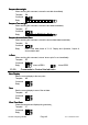
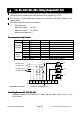
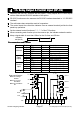
Pin connections and Circuits
Pin connections and CircuitsPin connections and Circuits
Pin connections and Circuits
Function Pin No. Signal name Direction Description
1 SDA Output Transmission A terminal
2 SDB Output Transmission B terminal
3 RDA Input Receive A terminal
4 RDB Input Receive B terminal
RS-422
RS-485
5 TRM - Terminator resistance(100)
6 HI Output Relay output HI
7 OK Output Relay output OK
8 LO Output Relay output LO
Relay
output
9 COM - Relay output common
Adaptable connector TM-BLA9 (of accessory)
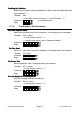
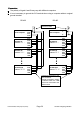
Switching Between RS
Switching Between RSSwitching Between RS
Switching Between RS-
--
-422/RS
422/RS422/RS
422/RS-
--
-485
485485
485
Switching between RS-422/RS-485 is made with the slide switch (SW1) on the
OP-03 board.
14. RS-422/485, Relay Output (OP-03)
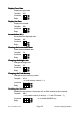
Relay Output Terminals
RS-422 Output
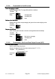
RS-485 Output
RS-422 Input
RS-485 Input
RS-422/RS-485 Terminals