FX-i SERIES FX-120i / FX-200i / FX-300i FX-1200i / FX-2000i / FX-3000i Precision Balance INSTRUCTION MANUAL WM+PD4001199
© 2006 A&D Company Ltd. All rights reserved. No part of this publication may be reproduced, transmitted, transcribed, or translated into any language in any form by any means without the written permission of A&D Company Ltd. The contents of this manual and the specifications of the instrument covered by this manual are subject to change for improvement without notice. Windows, Word and Excel are the registered trademarks of the Microsoft Corporation.
CONTENTS Basic Operation 1. INTRODUCTION .............................................................................................................................3 1-1 About This Manual.............................................................................................................................. 3 1-2 Features ............................................................................................................................................. 3 1-3 Compliance.......................
9-1 Structure and Sequence of the Function Table ................................................................................ 30 9-2 Display and Keys .............................................................................................................................. 30 9-3 Details of the Function Table ............................................................................................................ 31 9-4 Description of the Class “Environment, Display” ..............................
1. INTRODUCTION This manual describes how the FX-i series balance works and how to get the most out of it in terms of performance. Read this manual thoroughly before using the balance and keep it at hand for future reference. 1-1 About This Manual This manual consists of the following five parts: Basic operation ........................ Describes precautions on handling the construction and basic balance operation. balance, balance Adapting to the environment ....
2. UNPACKING THE BALANCE 2-1 Unpacking The balance is a precision instrument. Unpack the balance carefully. Keep the packing material to be used for transporting the balance in the future. The packing contents depend on the balance model. See the illustrations to confirm that everything is contained. How to assemble the breeze break (Only for FX-120i/200i/300i) Assemble the breeze break as shown below. Follow the numbered sequence.
2-2 Installing the Balance Install the balance as follows: 1. Place the balance on a solid weighing table. Refer to “3. PRECAUTIONS” for installing the balance. 2. FX-120i /200i /300i Assemble the pan support, weighing pan and breeze break, on the balance as shown in the illustration on page 4. FX-1200i /2000i /3000i Assemble the pan support and weighing pan on the balance as shown in the illustration on page 4. 3. Adjust the leveling feet to level the balance. Confirm it using the bubble spirit level. 4.
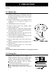
3. PRECAUTIONS To get the optimum performance from the balance and acquire accurate weight data, note the following: 3-1 Before Use Install the balance in an environment where the temperature and humidity are not excessive. The best operating temperature is about 20°C / 68°F at about 50% relative humidity. Install the balance where it is not exposed to direct sunlight and it is not affected by heaters or air conditioners. Install the balance where it is free of dust.
This balance uses a strong magnet as part of the balance assembly, so please use caution when weighing magnetic materials such as iron. If there is a problem, use the underhook on the bottom of the balance to suspend the material away from the influence of the magnet. Eliminate the temperature difference between a sample and the environment. When a sample is warmer (cooler) than the ambient temperature, the sample will be lighter (heavier) than the true weight.
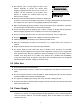
3-5 Display Symbols and Key Operation Key operation Key operation affects how the balance functions. The basic key operations are: “Press and release the key immediately” or “Press the key” = normal key operation during measurement “Press and hold the key” Display symbols Each key, when pressed or when pressed and held, functions as follows: Key When pressed When pressed and held Turns the display on or off. The standby indicator is displayed when the display is turned off.
4. WEIGHING UNITS 4-1 Units With the FX-i series balance, the following weighing units and weighing modes are available: A unit or mode can be selected and stored in the function table as described on page 11. If a weighing mode (or unit of weight) has been turned off, that mode or unit will be missing in the sequence. Tael has four varieties, one of which can be selected and installed at the factory. To select a unit or mode for weighing, press the MODE key.
The tables below indicate the weighing capacity and the minimum display for each unit, depending on the balance model. Unit Capacity FX-120i FX-200i FX-300i Minimum display Gram 122.000 220.000 320.000 0.001 Ounce (Avoir) 4.30340 7.76025 11.28765 0.00005 Pound 0.268965 0.485015 0.705480 0.000005 Pound/Ounce 0L 4.30oz 0L 7.76oz 0L 11.29oz 1L 0.01oz Troy Ounce 3.92240 7.07315 10.28825 0.00005 Metric Carat 610.000 1100.000 1600.000 0.005 Momme 32.2535 58.6665 85.3335 0.
4-2 Storing Units The units or modes can be selected and stored in the function table. The sequence of displaying the units or modes can be arranged in the function table so as to fit the frequency of use. Select a unit or mode and arrange the sequence of display as follows: 1 Press and hold the SAMPLE key until function table is displayed. ba5fnc of the 2 Press the SAMPLE key several times to display 1Unit . 3 Press the PRINT key to enter the unit selection mode.
5. WEIGHING 5-1 Basic Operation (Gram Mode) 1 Place a container on the weighing pan, if necessary. Press the RE-ZERO key to cancel the weight (tare). The balance displays 0.00 g. (The decimal point position depends on the balance model.) 2 Place a sample on the pan or in the container. 3 Wait for the stabilization indicator to be displayed. Read the value. While the stabilization indicator is on, pressing the PRINT key will output the weight value, using the RS-232C serial interface.
5-2 Counting Mode (PCS) This is the mode to determine the number of objects in a sample based on the standard sample unit mass. Unit mass means the mass of one sample. The smaller the variables in each sample unit mass are, the more accurate the counting will be. The FX-i series balance is equipped with the Automatic Counting Accuracy Improvement (ACAI) function to improve the counting accuracy. Note If the sample unit mass variable is too large, it may cause a counting error.
If the balance judges that the mass of the samples is too light to aquire accurate weighing, it displays an error requiring the addition of more samples to the specified number. In the example above, 150- PCS appears, requiring 25 more samples. Add 25 samples and press the PRINT key. When the unit mass is stored correctly, the balance proceeds to the counting mode. Counting operation 7 Place the samples to be counted on the pan.
5-3 Percent Mode (%) This is the mode to display the weight value in percentage compared to a 100% reference mass and is used for target weighing or checking the sample variable. Selecting the percent mode 1 Press the MODE key to select % (percent mode). Storing the 100% reference mass 2 Press the SAMPLE key to enter the 100% reference mass storing mode. Even in the storing mode, pressing the MODE key will switch to the next mode. 3 Place a container on the weighing pan, if necessary.
5-4 Statistical Calculation Mode The statistical calculation mode statistically calculates the weight data, and displays or outputs the results. To use the statistical calculation mode, set the "Application function (apf)" parameter of “Application (ap fnc)” in the function table to “2”, as described below. Statistical items available are number of data, sum, maximum, minimum, range (maximum-minimum), average, standard deviation and coefficient of variation.
Selecting the statistical items to output 5 Press the SAMPLE key to display 5taf 0 . 6 Press the RE-ZERO key to select the output items. In the example, 5taf 1 is selected to output the number of data, sum, maximum, minimum, range (maximum-minimum) and average.
1 Press the RE-ZERO key to set the display to zero. 2 Place the sample on the weighing pan and wait for the stabilization indicator to turn on. 3 Press the PRINT key to add the data displayed to statistical calculation. The number of data on the upper left of the display increases by 1. 4 Repeat steps 1 to 3 for each weighing.
Deleting the latest data When the wrong data is entered, it can be deleted and excluded from statistical calculation. Only the latest data can be deleted. 1 In the weighing mode, press the MODE key, and then press the SAMPLE key several times to display 1CanCel . 2 Press the PRINT key to display Can no . 3 Press the RE-ZERO key to display Can go . 4 Press the PRINT key to delete the latest data and exclude it from statistical calculation.
5-5 Statistical Calculation Mode (Example of Use) Here, as an example of use of the statistical calculation mode, mixing of the multiple formulae such as medicine is described. The mixing process is recorded using the balance and the printer. In the example, the FX-3000i and the AD-8121B (dump print mode) are connected using the RS-232C serial interface.
5-5-2 Using The Statistical Calculation Mode 1 Press the RE-ZERO key to set the display to zero. 2 Place a container on the weighing pan. Press the PRINT key to cancel the weight (tare). The balance displays 0.00 g. (Storing the tare value) The tare value data is output when the peripheral output equipment is connected. 3 Weigh formula 1 and press the PRINT key. The balance displays 0.00 g.
6. RESPONSE ADJUSTMENT This function stabilizes the weight value, reducing the influence on weighing that is caused by drafts and vibration at the place where the balance is installed. The function has three stages as follows and can be changed by simple key operation. Indicator FAST Description Fast response, but prone to drafts and vibration. Good for target weighing. MID. SLOW Slow response, but strong against drafts and vibration Good for weighing which requires a stable display.
7. CALIBRATION 7-1 Calibration Mode The FX-i series balance has the following two modes. Calibration using an external weight Calibration test using an external weight (Calibration test does not perform calibration.) Terms The following terms are defined as follows: External weight = A weight that you have. Referred to as a calibration weight when used for calibration.
7-2 Calibration Using an External Weight This function calibrates the balance using an external weight. Operation 1 Connect the AC adapter and warm up the balance for at least 30 minutes with nothing on the pan. 2 Press and hold the CAL key until displayed, and then release the key. 3 The balance displays Cal Calout is 0. If you want to change the calibration weight (a list of usable weights is shown on page 23), press the SAMPLE key and proceed to step 4.
5 Confirm that there is nothing on the pan and press the PRINT key. The balance measures the zero point. Do not allow vibration or drafts to affect the balance. The balance displays the calibration weight value. 6 Place the displayed calibration weight on the pan and press the PRINT key. The balance measures the calibration weight. Do not allow vibration or drafts to affect the balance. 7 The balance displays from the pan. end .
7-3 Calibration Test Using an External Weight This function tests the balance weighing accuracy using an external weight and outputs the result. This is available only when the “GLP output (info)” parameter is set to “1” or “2”. (Calibration test does not perform calibration.) Operation 1 Connect the AC adapter and warm up the balance for at least 30 minutes with nothing on the pan. 2 Press and hold the CAL key until displayed, and then release the key. CCout is 3 The balance displays CC 0 .
5 Confirm that there is nothing on the pan and press the PRINT key. The balance measures the zero point and displays the measured value. Do not allow vibration or drafts to affect the balance. The balance displays the target weight value. 6 Place the displayed target weight on the pan and press the PRINT key. The balance measures the target weight and displays the measured value. Do not allow vibration or drafts to affect the balance. 7 The balance displays pan. end .
8. FUNCTION SWITCH AND INITIALIZATION 8-1 Permit or Inhibit The balance stores parameters that must not be changed unintentionally. There are two switches for the purpose of protecting these parameters. Each switch can select either “permit” or “inhibit”. The “inhibit” protects parameters against unintentional operations. Switches Operation 1 Press the ON:OFF key to turn off the display. 2 While pressing and holding the PRINT key and the SAMPLE key, press the ON:OFF key. The balance displays p5 .
8-2 Initializing the Balance This function returns the following parameters to factory settings. Calibration data Function table The sample unit mass value (counting mode), 100% reference mass value (percent mode) External calibration weight Function switch settings Statistical data Note Be sure to calibrate the balance after initialization. Operation 1 Press the ON:OFF key to turn off the display. 2 While pressing and holding the PRINT key and the SAMPLE key, press the ON:OFF key.
9. FUNCTION TABLE The function table reads or rewrites the parameters that are stored in the balance. These parameters stored, even if the AC adapter is removed, are maintained in non-volatile memory. 9-1 Structure and Sequence of the Function Table The function table menu consists of two layers. The first layer is the “Class” and the second layer is the “Item”. Each item stores a parameter. Example This example sets “Auto print mode A” for “Data output mode” and “100 digits” for “Auto print difference”.
9-3 Details of the Function Table Class Item and Parameter Cond Condition 5t-b Stability band width Hold Hold function trc Zero tracking ba5fnc Environment 5pd Display Display refresh rate pnt Decimal point p-on Auto display-ON poff Auto display-OFF rng Display at start beep Beep Cp Comparator mode Cp fnc bepComparator LO buzzer bepOK buzzer bepHI buzzer Cp Hi Upper limit Cp lo Lower limit Description 0 1 2 0 1 2 0 1 0 1 2 3 0 1 2 0 1 0 1 0 1 0 1 0 1 0 1 2 3 4 0 1 0 1 0 1 Fast response, sensitive value
Class Item and Parameter Description 0 3 Auto print mode A (Reference = zero) Auto print mode B (Reference = last stable value) Stream mode 4 Key mode B (Immediately) 5 Key mode C (When stable) 6 0 1 2 0 1 2 0 1 2 3 4 5 Interval output mode Plus only Minus only Both 10 digits 100 digits 1000 digits Every measurement 2 seconds 5 seconds 10 seconds 30 seconds 1 minute 2 minute 5 minute 10 minute No pause Pause (1.
Class Item and Parameter bp5 Baud rate btpr Data bit, parity bit 5if Serial interface Crlf Terminator type Data format t-Up Timeout erCd AK, Error code mltMLT Programmable-unit (Multi-unit) Unit Unit id ID number apf Application function ap fnc Application 5taf Statistical function mode output items Description 0 1 2 3 4 5 0 1 2 0 1 0 1 2 3 4 5 0 1 0 1 600 bps 1200 bps 2400 bps 4800 bps 9600 bps 19200 bps 7 bits, even 7 bits, odd 8 bits, none CR LF CR A&D standard format DP format KF format MT for
9-4 Description of the Class “Environment, Display” Condition ( Cond ) Cond 0 Cond 2 This parameter is for sensitive response to the fluctuation of a weight value. Used for powder target weighing, weighing a very light sample or when quick response weighing is required. After setting, the balance displays FAST. This parameter is for stable weighing with slow response. Used to prevent a weight value from drifting due to vibration or drafts. After setting, the balance displays SLOW.
Zero tracking ( trc ) This function tracks zero point drift caused by changes in the environment and stabilizes the zero point. When the weight data is only a few digits, turn the function off for accurate weighing. Note Digit, when used for the FX-i series balance, indicates a unit of minimum weighing value. trc trc trc trc 0 1 2 3 The tracking function is not used. Used for weighing a very light sample. The tracking function is used. Normal zero tracking. The tracking function is used.
9-5 Description of the Item “Data Output Mode” The parameter setting of the “Data output mode ( prt )” applies to the performance when the data is transmitted using the RS-232C serial interface. Key mode When the PRINT key is pressed with the stabilization indictor turned on, the balance outputs the weight data and the display blinks one time.
Interval output mode The weight data is periodically output. When the PRINT key is pressed, the balance starts to output the weight data at a preset interval time. When the PRINT key is pressed again, the balance stops outputting the weight data. Required setting Example dout prt 6 Interval output mode dout int Interval time “For outputting the weight data periodically." Caution The balance may not transmit the data completely at the specified interval times and baud rate. Set the baud rate higher.
KF format 5if type 2 This is the Karl-Fischer moisture meter format and is used when the peripheral equipment can only communicate using this format. This format consists of fourteen characters excluding the terminator. This format has no header characters. The polarity sign is placed before the data, with spaces in place of leading zeros, if the data is not zero or overloaded. This format outputs the unit only for a stable value.
9-7 Data Format Examples
Note When “Pound Ounce” is selected, the data is output with the unit of ounce (oz). 9-8 Description of the Item “Application Function” Capacity indicator ( apf 1) In the weighing mode, the indicator displays the weight data relative to the weighing capacity in percentage. (Zero = 0%, maximum capacity = 100%) Statistical calculation mode ( apf 2) The mode statistically calculates the weight data, and displays or outputs the results. For details, refer to “5-4 Statistical Calculation Mode”.
9-9 Comparator Function The results of the comparison are indicated by HI OK LO on the display.
10. ID NUMBER AND GLP REPORT The ID number is used to identify the balance when Good Laboratory Practice (GLP) is used. The ID number is maintained in non-volatile memory even if the AC adapter is removed. The GLP output format is selected at “GLP output (info)” of the function table and can be output to a personal computer or printer using the RS-232C serial interface.
Calibration report using an external weight When the setting is “info 1”: When the setting is “info 2”: Calibration test report using an external weight (Calibration test does not perform calibration.
Title block and end block When a weight value is recorded as the GLP data, “Title block” and “End block” are inserted at the beginning and at the end of a group of weight values, in the GLP report. Note To output the report to an AD-8121B , use MODE 3 of the AD-8121B. Operation 1 With the weight data displayed, press and hold the PRINT key until S5tart The “Title block” is output. is displayed. 2 The weight data is output according to the parameter setting of the data output mode.
11. UNDERHOOK The underhook can be used for magnetic materials or density measurement. The built-in underhook is revealed by removing the plastic cap on the bottom of the balance. Use the underhook as shown below. Bottom of the balance Underhook Cap Caution Do not apply excessive force to the underhook. When not in use, attach the plastic cap to prevent dust from getting into the balance.
12. PROGRAMMABLE-UNIT This is a programmable unit conversion function. It multiplies the weight data in grams by an arbitrary coefficient set in the function table and displays the result. The coefficient must be within the range between the minimum and maximum shown below. If the coefficient set is beyond the range, an error is displayed and the balance returns to the coefficient setting mode, prompting to enter an appropriate value. A coefficient of 1 was set at the factory.
13. RS-232C SERIAL INTERFACE The balance is a Data Communication Equipment (DCE) device. Connect the balance to a personal computer (DTE) using a straight through cable.
14. CONNECTION TO PERIPHERAL EQUIPMENT 14-1 Connection to the AD-8121B Printer Set the following parameters to use the AD-8121B printer. Example of use AD-8121B mode setting To print A&D standard format weight data, using the FX-i PRINT key MODE 1 or FX-i auto print mode. (The time and date can be added.) To print A&D standard format weight data, using the AD-8121B DATA key or AD-8121B built-in timer. (The time and date can be added.) MODE 2 To print, using the AD-8121B chart printing function.
14-2 Connection to a Computer The FX-i series balance can be connected to a personal computer using the RS-232C serial interface. As an option, the FXi –02 USB interface is available to transmit the balance data to a personal computer. The FX-i series balance is a DCE. Use a straight through cable. If purchasing the RS-232C cable on the market, check the interface connections and type.
Using the WinCT software, the balance can do the following: 1 Analyzing the weight data and the statistics with “RsKey” The weight data can be input directly into an Excel worksheet. Then, Excel can analyze the data to obtain sum, average, standard deviation, maximum and minimum value, and display them in a graph.
15. COMMANDS 15-1 Command List Note A command has a terminator added, that is specified using the "Terminator (Crlf)" parameter of “Serial interface ( 5if )” in the function table, and is sent to the balance. Commands to query weight data C Q S SI SIR E SCP Cancels the S or SIR command. Requests the weight data immediately. Requests the weight data when stabilized. Requests the weight data immediately. Requests the weight data continuously. Requests the weight data when stabilized.
15-2 Acknowledge Code and Error Codes When the “AK, Error code (erCd)” parameter of “Serial interface ( 5if )” is set to “1”, the balance outputs code or an error code for each command as follows: (06h) Acknowledge in ASCII code. When the balance receives a command to request data and can not process it, the balance transmits an error code (EC, Exx). When the balance receives a command to request data and can process it, the balance outputs the data.
T command example PT command example When a communication error has occurred due to external noise, or a parity error has occurred due to transmission error, the balance transmits an error code. In this case, send the command again. 15-3 Settings Related to RS-232C Concerning the RS-232C, the balance has two functions: “Data output ( dout )” and “Serial interface ( 5if )”. Set each function as necessary.
16. MAINTENANCE Do not use organic solvents to clean the balance. Clean the balance with a lint free cloth that is moistened with warm water and a mild detergent. Do not disassemble the balance. Contact the local A&D dealer if the balance needs service or repair. Use the original packing material for transportation.
17. TROUBLESHOOTING 17-1 Checking the Balance Performance and Environment The balance is a precision instrument. When the operating environment or the operating method is inadequate, correct weighing can not be performed. Place a sample on the pan and remove it, and repeat this several times. If the balance seems to have a problem with repeatability or to perform improperly, check as described below. If improper performance persists after checking, contact the local A&D dealer for repair.
17-2 Error Codes Display Error code EC, E11 Description Stability error The balance can not stabilize due to an environmental problem. Prevent vibration, drafts, temperature changes, static electricity and magnetic fields. Refer to “3. PRECAUTIONS” for details on the operating environment and “6. RESPONSE ADJUSTMENT” about adapting the balance to the environment. To return to the weighing mode, press the CAL key. Out of range error The value entered is beyond the settable range. Re-enter the value.
Display Error code EC, E00 Description Communications error A protocol error occurred in communications. Confirm the format, baud rate and parity. EC, E01 Undefined command error An undefined command was received. Confirm the command. EC, E02 Not ready A received command can not be processed. e.g. The balance received a Q command, but not in the weighing mode. e.g. The balance received a Q command while processing a RE-ZERO command. Adjust the delay time to transmit a command.
18. OPTIONS Note The FXi-02, FXi-08 and FXi-09 can not be used at the same time. FXi-02 USB interface (Installed in the balance, Applicable OS: Windows 98 OSR2 or later) Used to transmit the balance weight data (numerical value only) uni-directionally to a personal computer via USB. Can transmit the balance weight data (numerical value only) directly to other application software such as Microsoft Excel, Word and memo pad. Driver installation is not necessary.
AX-FXi-31 Main unit cover Main unit protective cover provided as standard. AD-1683 DC static eliminator Used to minimize weighing errors due to static electricity on the material. AD-8920 Remote display Connected to the FX-i series balance using the RS-232C serial interface to display the weight data away from the balance. AD-8922 Remote controller Connected to the FX-i series balance using the RS-232C serial interface to display the weight data and to remotely control the balance.
19. SPECIFICATIONS FX-120i FX-200i FX-300i FX-1200i FX-2000i FX-3000i Weighing capacity 122 g 220 g 320 g 1220 g 2200 g 3200 g Maximum display 122.084 g 220.084 g 320.084 g 1220.84 g 2200.84 g 3200.84 g Minimum weighing value (1 digit) 0.001 g 0.01 g Repeatability (Standard deviation) 0.001 g 0.01 g Linearity ±0.002 g ±0.02 g Stabilization time (typical at FAST) Approx.
20. EXTERNAL DIMENSIONS FX-120i / 200i / 300i 193 262.5 171.5 (*2) 70.5 81 175 φ130 (*3) 184 115 (*1) 168.5 83.5 (*5) 171.5 (*2) 84.5 85 (*4) 184 115 (*1) 61.5 162 194.5 *1: Width of the opening when a clear plate is removed *2: Inside dimension *3: Weighing pan diameter *4: Height from the weighing pan up to the cap of the breeze break (Inside dimension) *5: Height of the opening when a clear plate is removed FX-1200i / 2000i / 3000i 193 262.5 φ150 70.5 84.5 168.5 162 61.5 194.
21. TERMS/INDEX Terms Stable value The weight data when the stabilization indicator appears. Environment Ambient conditions such as vibration, drafts, temperature, static electricity and magnetic fields which affect the weighing operation. Calibration Adjustment of the balance so that it can weigh accurately. Output To output the weight data using the RS-232C serial interface. Zero point A weighing reference point or the zero display.
Index Keys and symbols ON/OFF key ..............................8 SAMPLE key .............................8 MODE key .............................8, 9 CAL key .........................8, 24, 26 PRINT key .................................8 RE-ZERO key..................7, 8, 12 Stabilization indicator..............8 Interval output mode active indicator ....8 Interval output mode standby indicator ..8 Processing indicator ...............8 CR ..........................................39 LF ....................
DC static eliminator.............................59 DCE ......................................47, 49 Decimal point .............................. 31, 35 Digit ................................31, 35, 62 Display at start ....................................31 Display refresh rate.......................31, 35 dout Data output .........................32 DP format......................................33, 37 DTE ............................................47 -E-e ............................................
Number of data.............................16, 33 -OON:OFF key ...................................8, 28 Operating environment .......................60 -PPan support ..........................................4 Parity ............................................47 pcs ............................................13 Percent Mode .....................................15 Permit ............................................28 pnt Decimal point ................31, 35 poff Auto display-OFF..........
MEMO
MEMO
MEMO
13
3-23-14 Higashi-Ikebukuro, Toshima-ku, Tokyo 170-0013 JAPAN Telephone: [81] (3) 5391-6132 Fax: [81] (3) 5391-6148 http://www.aandd.co.jp/ A&D ENGINEERING, INC. 1555, McCandless Drive, Milpitas, CA. 95035 U.S.A. Telephone: [1] (408) 263-5333 Fax: [1] (408)263-0119 A&D INSTRUMENTS LTD.