ОМПГ^Щ©ТГО©М ffiQÄMMÄlL owners-AD-8118A-V.3.a 90.11.
Table of Contents Warranty..................................................................................................... Page3 Compliance with FCC Rules................................................................... Page 3 Introduction Welcome.....................................................................................................Page4 Features..................................................................................................... Page4 Specifications............ ........
Printing Nornnal Characters.................................................................................... Page22 Enlarged Characters.................................................................................. Page23 Applications Serial Inputs............................................................................................... Page26 Connection to an Industrial■>Scale.............................................................. Page26 Connection to an Electronic Balance................
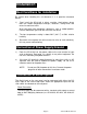
Warranty Warranty rights vary from country to country but it is the general intention of A&D Co., Ltd., to offer customers a one year warranty on this product from the day it is purchased. In some countries consumer protection legislation states that your dealer is responsible for offering a warranty and under these circumstances please ^efer to your local dealer. in the U.S.A. the product (if defective) should be returned, freight prepaid by the customer, to A&D Engineering Inc.
Introduction Welcome! Thank you for your purchase This is an Instruction Manual for the AD-8118 A Journal printer. The AD-8118A is a product of years of design, development, and in-field testing. It is designed to withstand harsh environmental conditions - and each printer is subjected to several levels of quality control before it leaves the factory.
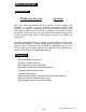
Specifications Printer Specifications Printing system Printing width > Printing speed Dimensions of character Reiiability ink ribbon (ERC-09) Color of character Mechanical type dot impact printer 24 columns/iine for 5 x 7 dot character 12 columns/Iine for 10 x 7 dot character (enlarged character) Approximately 1.7 iine/second (internal processing time excluded) 1.7(W)x2.6 (H) mm 3.4 (W) X 2.
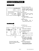
Description of Panels Front Panel © Cover for setting section Remove this cover and use the DIP switches to set, otherwise keep it attached to prevent dust from getting inside. @ @ Printer cover Remove this cover to change printing paper and/or ink ribbon,
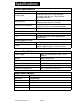
Accessories AC cable Fuse 0.5A lOOVtO 120V{blow) 0.3A 200V to 240V(blow) owners-AD-8118A-v.3.
Installation Best Conditions for installation Be careful when handling this unit because it is a precision electronic device. 1) Don't install the AD-8118A in direct sunshine. Avoid places where there are sudden temperature changes, vibrations, strong winds and excessive moisture or dirt. Also, keep away from conductive substances such as carbon powder. If these substances get inside the unit errors can occur. 2) The best temperature setting is about 20°C (68*^ F) at 50% relative humidity.
Using the Optional Interface The Serial input can be connected with a RS-232C input or current loop input using an RS-232C optional interface. This can be done with the FX, FY, FR, FV, FW and AD-4316 or AD-4321. (If the option is provided with a current loop output, it can be used as well.) Note that these units^are equipped with outputs that can be connected to the AD-8917, AD-8918, AD-8117 and AD-8118A externally. Serial Input Connection Table Pin No. 1 2 3 4 5 6 7 Abbreviation C.LOUT F.G Ser.
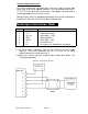
Connection of Control I/O +v Input □ □ □ This is the interface circuit of the Control I/O . Please use an optical isolator or relay. The extension, or driving capacity of these relays is 24V 50mA DC maximum. The width of these inputs are at least 100msec. □ Control I/O Connection Table Pin No. Description Pin No.
Replacing the Printing Paper 1, First, turn the power OFF. I---- 1 Front View o0 r 2. Loosen the screws on the printer cover and draw out the printer unit. 3. Peel off the adhesive tape on the printing paper (PP-137) completely, insert the shaft provided as an accessory and set the paper. (Be careful of the Erection of the paper.) 4.
Replacing the Ink Ribbon 1. First, turn the power OFF. 2. Loosen the screws on the printer cover and draw out the printer unit. Remove the printing paper. (Refer to "Replacing the Printing Paper," p. 10.) 3. Remove the printer cover carefully: it can be detached from the unit by lightly lifting up. 4. Remove the old ink ribbon by lifting it up when the arrow position of the printer unit is pushed. 5. Set the new ink ribbon in place being careful not to roll the ribbon.
Settings Setting the DIP Switches The DIP switches control the conditions of printing. Open the cover on the front panel (refer to “Front Panel,“ p. 6) and set the DIP switches. The DIP switch options are as follows: ON OFF Contents Switch No.
T h e Standard format results in data after the output from an A&O industrial scale or electronic balance is internally processed and formatted. Printing timing, cumulative total, etc. are taken, (For the input data of the standard format, refer to "Applications," p. 21.) Printing form Switch #4 Select the printing direction. 12/31/99 11:59 PM 600.
The FEED key will advance the paper by one line and the PRINT key will print the function message and the data currently in the setting format. Press and immediately release the SET UP key to update and escape the Function mode. The functions will be printed and the unit will return to setting mode. F1-1,F2-2,F3-1,F4-1 FUNCTION SET END Function Mode Options F1-Printing Mode There are two types of FI printing modes: (1) The Auto mode prints input data automatically.
F4- Statistics mode This mode can get maximum data .minmum data ,average data .standard deviation, sample range of cumulated data and prints out these. The Statistics caluclates all data no concernning with code data. mode Set value of F4 F4-0 No caluclation of statistics (initial setting) F4-1 Sample deviation (an-i) F4-2 Standard deviation (an) Time Setting Mode Press the TOTAL key while at the same time pressing the SET UP key. Now change the date and time to their correct settings.
Date Formatting Mode You can select from the following date formats: American type: European type: Japanese type: 6/22/90 10:47 AM 22/6/90 10:47 AM 90*6*22* 10*47* AM To change date format: Step 1 Turn off the power switch on the rear panel. Step 2 Turn back on the power switch while pressing the SET UP key and M+.PRT key at the same time. Step 3 Press the CLEAR key to rotate through the three types. The type selected will be printed as the CLEAR key is pressed.
Operation Operating the Switch Keys PRINT FEED FEED key Press this key to advance one line. Hold it pressed to feed continuously. SET UP M+.PRT PRINT* key Press this key to print a line of data input. If no data is input within 3 seconds, "T ERROR" will be printed. If the format does not match, "F ERROR" will be printed. M+.PRT* key Press this key to add an input data before printing. If no data is input within 3 seconds a "T ERROR" is printed. If the format does not match, "F ERROR" is printed.
Operating the Control I/O Inputs Code The value is printed on the left side of the paper when addition printing is done. This value is stored with the we^ht value and can be retrieved by code as well. This code is not printed if the value is "00," only numbers from 01 to 99 can be used. Print command* When this input is negative low (short), the first data input within 3 seconds is printed. Paper feed command This command advances the paper one line, negative low(short).
The inputs marked with are disabled in Auto printing mode. In Dump printing, all functions except paper feed are disabled. Each command input is judged at the negative edge and actuated only when it is turned ON. Input is accepted when turned ON (short-circuited) continuously for 100 ms or longer. Page 20 owners-AD-8118A“V.3.
others Printing buffer This unit has a printing buffer of 80 lines. If data can not be printed the data is stacked in this buffer and cleared as the printing progresses. If this buffer exceeds 75 lines the "Busy Output" from the I/O is turned ON. "B ERROR" is printed^ once when the buffer exceeds 80 lines. The printing speed is 1.7 iines/sec, do not input the data faster than this speed.
Printing Normal Characters Normal printing Greater Code 8^11/99 8S00 PiH CD99 -Weight value (3S+ 200.0kg. Code number Addition printing S/n/99 8:90 AM # ,1 CD99 9S+ 200,0kg ACumulative total counting number Error code is printed from prior Error code. Code priority as follow : O ERROR>S ERROR>U ERROR>F ERROR>l ERROR Reference page 21 Cumulative total by Code is not Printed, when only 'Code No.OO' is entered, and No other Code No is followed. (Control I/O is not connected).
Grand Total printing (Cumulative total by code (times : 4 digits, cumulative total: 9 digits) GRAND TOTAL 9/11/99 18:05 PM 50.02kg0 IT CO 1 IT 3.012k9 C099 IT 200.0kg3T 253.032kg- ;/■■Gross cumulative total (times ; 6 digits, cumulative total: 11 digits) GRAHD TOTAL 8/11/99 10:06 PM 50 0.02k9. 3..0l2k9 f ^Cumulative total by code (times : 4 digits, cumulative total : 9 digits) /( 200 253.032kg—Gross cumulative total (times : 6 digits, 200kg ' ® cumulative total: 11 digits) 3.012kg 84.
Subtotal Printing Error code Number of times SUE/ TOTAL > S/1l/99>40:05 PM X kD IT^ • 50- 02 kg CD 1 IT 3- 012kg IT CD33 200- 0 kg■ 3T 253-032kg cumulative total: 11 digits) 3UB XOTAU 8/11/99 10!06 PM o IT S0. Q2 k*3 CD 1 ^Cumulative total by code (times : 4 digits, j cumulative total: 9 digits) IT 3.012 IT 200.
Grand Total Printing aRAND TQTi^L. 3/n>^9 18i0S PH O IT •l—* CD 1 K ^SmF XT Cumulative total by code (times : 4 digits, cumulative total: 9 digits) 3-©X2k3 1T 200« ©k-g 3T 233. 032 0Ri=^HD TOTAU S/U/9S 18:06 PH O XT CD X MAX ise . 02 k-s XT 3. 0X2k-g XT Gross cumulative total (times : 6 digits, cumulative total: 11 digits) ,Cumulative total by code (times ; 4 digits, cumulative total: 9 digits) 200.0 k-g _l^ Gross cumulative total (times ; 6 digits, 2S3.
Applications Serial Inputs The serial input can be changed through the RS-232C to current loop by the slide switch on the rear panel. Select either one depending on the product being connected. The power for the current loop is supplied by the receiving side.
* 2 A unit with ”(OP-xx)" can connect to the standard serial output. Please set the DIP switches according to the specifications of these units. When connecting to an AD-4325A, cumulative total can be started by the codes of the AD-4325A if set to the output of format with the correct code. Set the printer mode on DIP switch #3 to standard format. AD-4601 has RS-232C. Set print mode of RS-232C Function . you can input standard format data.
Connection to Other Devices if this printer is connected to a personal computer, a sequencer or any other unit set this unit to the RS-232C and Dump print. Set the DIP switches appropriately. For characters to print, refer to the "Character Code Table” in the Appendix, p. 30. This unit only receives signals, it can't output control signals, message, etc. Note that overflow of the data buffer is valid for control I/O only. > The following codes have meaning as control signals: ODH........
Il^ Dimensions SIDE VIEW 186 + 1.0 + 0.8 0 owners-AD-8118A-v.3.
Appendix Character Code Table KEX.
A&D Company Limifed Oashalsu-NIssay Ikebukuro Bldg. 5F, 3-23*14 HigashWkebukufo, Toshima-ku, Tokyo 170 Japan Telephone: (03) 5391-6123 Fax: {03} 5391-6129 Telex: 02422816 AANOD J A&DWGINEOTNG,1MC. 1555 McCandless Drive, Mtipilas. CA, 95035 U.SA Telephone: (408) 263-5333- Fax; (408) 263-0119 A8tD INSTRUMENTS GmbH Lyoner Straße 36, 0-6000 Frankfurt/Main 71. West Germany Telephone: (069) 666-7006 Fax: (069) 566-6831 Telex: 417 0586 ANDI D A8cD MERCURY PTY LTD. 32 Dew Street, Thebarton.