
Owner manual


24
5. SecureassemblytoroofstructureasshowninFigureEusing
fieldsuppliedmetalstrappingorequivalentsupportmaterial.
NOTE: Ensure termination height is above the roof surface or
anticipated snow level (1 ft. in U.S.A. or 1-1/2 ft. in Canada) as
shown in Figure C.
6. Install rain cap and small diameter pipe assembly in
ro of penetr ati on a ssembly, Ens ure small dia met er p ipe
is cemented and bottomed in Y concentric fitting.
7. Cement water heater combustion air intake and vent pipes to
concentric vent termination assembly. See Figure E for
properpipeattachment.
8. Operateheater through 1heat cycle to ensure combustionair
andventpipesareproperlyconnectedtoconcentricventtermination
connections.
NOTE: All vent terminations must be the same height when
installing multiple unit venting. If assembly is too short to meet
height requirement, the 2 pipes supplied in the kit may be replaced
by using same diameter, eld supplied SDR-26 PVC (D2241) pipe.
Do not extend the 21-1/8” dimension outer pipe to be more than
60 inches, see Figure B.
CAUTION
Do not use eld-supplied couplings to extend pipes. Airow
restriction will occur and the heater pressure switch may cause
intermittent operation.
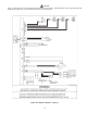
PROCEDURE 2 SIDE WALL TERMINATION, see Figure F.
FIGURE F.
1. Determinebestlocationforterminationkit.
NOTE: Consideration for the following should be used when
determininganappropriatelocationfortheterminationkit:
• Termination kit positioned where the vent vapors will
n o t d a m a g e p l a n t s / s h r u b s o r a i r c o n d i t i o n i n g
equipment.
• Termination kit positioned so it will not be affected by
wind eddy that may allow recirculation of combustion
products,orairborneleaves,orlightsnow.
• Termination kit positioned where it will not get damaged
or be subjected to foreign objects, such as stones,
balls, etc.
• Termination kit positioned where the vent vapors will
notbeobjectionable.
NOTE: See the venting information (pages 16-20) in this
manual for additional vent location requirements.
2. Cut1hole(5in.diameter)
3. P a r t i a l ly a s s e m b l e co nc e n t r i c v e n t te r mi n a t i o n k i t .
a) Cement the Y concentric fitting to larger diameter
kitpipe,seeFigureA.
b) Cem ent th e rain cap to the small er dia meter kit
pipe,seeFigureA.
NOTE: Instead of cementing the smaller pipe to the rain cap, a
eld-supplied stainless steel screw may be used to secure the
2 components together when eld disassembly is desired for
cleaning, see Figure D.
WARNING
When using alternate screw assembly method, drill clearance
hole in rain cap and pilot hole in vent pipe for screw being
used. Failure to drill adequate holes may cause cracking
of PVC components, allowing combustion products to be
recirculated. Failure to follow this warning could result in
personal injury or death.
WARNING
Do not ope ra te the heat er with rain ca p removed or
recirculation of combustion products may occur. Water may
also collect inside larger combustion-air pipe and flow to the
burner enclosure. Failure to follow this warning could result
in product damage or improper operation, personal injury
or death.
4. Install Y concentric fitting and pipe assembly through
structure’shole.
NOTE: Do not allow insulation or other materials to accumulate
inside pipe assembly when installing through hole.
5. Install rain cap and small diameter pipe assembly in
Y concentric fitting and large pipe assembly. Ensure
small diameter pipe is bottomed and cemented in Y
concentrictting.
6. SecureassemblytostructureasshowninFigureGusingeld-
suppliedmetalstrappingorequivalentsupportmaterial.
NOTE: Ensure termination location clearance dimensions are as
shown in the diagrams found in Figure 15 A through D. When
extending the length of the 4” pipe, the added length beyond
21-1/8” must be deducted from the maximum equivalent feet of
vent pipe.
NOTE: If assembly needs to be extended to allow side
wall thickness re qu ir em en t, the 2 pipes su pp li ed in
the kit may be replaced by using same diameter, field-
sup p l i ed SD R - 2 6 PVC ( D 2 241) p i p e . Do n o t exte n d
21 1/8” dimension more than 60 in. (See Figure B.)
CAUTION
Do not use eld-supplied couplings to extend pipes. Airow
restriction will occur and the heater pressure switch may cause
intermittent operation.
7. Cement heater combustion-air and vent pipes to concentric
vent termination assembly. See Figure G for proper pipe
attachment.