CYCLONE XHE® Model BTH 120-250(A) SERIES 970 AND 973 COMMERCIAL GAS WATER HEATER GAS-FIRED POWER BURNER FOR DOMESTIC HOT WATER • INSTALLATION • OPERATION • SERVICE • MAINTENANCE • LIMITED WARRANTY WARNING: If the information in these instructions is not followed exactly, a fire or explosion may result causing property damage, personal injury or death. – Do not store or use gasoline or other flammable vapors and liquids in the vicinity of this or any other appliance.
CYCLONE XHE BTH 120 - 250 ROUGH-IN-DIMENSIONS GAS VALVE PIPING BTH-120 1/2" NPT BTH-150, 199 & 250 3/4" NPT Table 1. RECOVERY CAPACITIES - NATURAL GAS / L.P. Model Input BTU/Hr. Approx. Gallon Capacity 30 40 50 60 70 80 90 100 110 120 130 140 BTH - 120 BTH - 120 BTH - 150 BTH - 150 BTH - 199 BTH - 199 BTH - 250 125,000 Nat. 120,000 L.P. 150,000 Nat. 150,000 L.P. 199,900 Nat. 185,000 L.P. 240,000 Nat.
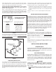
TABLE OF CONTENTS PAGE ROUGH-IN DIMENSIONS ................................................................... 2 FOREWORD ...................................................................................... 2 FEATURES ........................................................................................ 3,4 Water Temperature Control .......................................................... 3 High Limit Switch (E.C.O.) ............................................................
that the water temperature be set for the lowest temperature which satisfies your hot water needs. This will also provide the most energy efficient operation of the water heater and minimize scale formation. Continued manual resetting of high limit control, preceded by higher than usual water temperature is evidence of high limit switch operation. The following are possible reasons for high limit switch operation. SETTING THE WATER HEATER TEMPERATURE AT 120°F/49°C WILL REDUCE THE RISK OF SCALDS.
• Do not cover the temperature & pressure relief valve. • Do not cover the instruction manual. Keep it on the side of the water heater or nearby for future reference. • • Devices that will turn off the gas supply to a gas water heater while at the same time shutting off its water supply. WARNING THIS WATER HEATER IS A CONDENSING UNIT AND REQUIRES A DRAIN TO BE LOCATED IN CLOSE PROXIMITY TO ALLOW THE CONDENSATE TO DRAIN SAFELY.
ALCOVE less than 100 square inches (645 cm²). HARD WATER If the confined space is within a building of tight construction, air for combustion and ventilation must be obtained from outdoors. When directly communicating with the outdoors through vertical ducts, two permanent openings, located in the above manner, shall be provided. Each opening shall have a free area of not less than one square inch (6.5 cm²) per 4000 Btuh of the total input of all appliances in the enclosure.
DIRECT VENT *NOTE: BTH 250 USES TEE ON AIR INTAKE TERMINAL FIGURE 5 DO NOT TERMINATE EXHAUST OVER PUBLIC AREA WHERE CONDENSATE OR VAPOR CAN CAUSE NUISANCE OR HAZARD. HORIZONTAL VENT FIGURE 6 7 ON DIRECT VENT INSTALLATIONS, EXHAUST VENT HOOD MUST BE LOCATED 1' (30.5cm) MINIMUM FROM ANY OPENING IN BUILDING. ON DIRECT VENT INSTALLATIONS, EXHAUST VENT HOOD MUST BE LOCATED 4' (122cm) MINIMUM FROM ANY OPENING IN BUILDING.
TRANSMITTED INTO THE LIVING SPACES. THE AIR INTAKE (see Figure 8) PROVIDED ON THE UNIT. IMPORTANT The vent system must terminate so that proper clearances are maintained as cited in local codes or the latest edition of the National Fuel Gas Code, ANSI Z223.1/NFPA 54 and for Canadian installations consult the Canadian Installation Codes and CAN/CGA B149.1 and .2. 1. Do not terminate the exhaust vent terminal over public area where condensate or vapor can cause nuisance or hazard. 2.
FIGURE 9 IMPORTANT WHEN LOCATING THE TERMINALS ON A SIDEWALL, THE FOLLOWING SPECIFICATIONS PERTAINING TO TERMINAL LOCATION MUST BE FOLLOWED. 1. The intake vent terminal and the exhaust vent terminal must terminate on the same exterior wall and must be located at a minimum of 24" (61cm) from the vertical centerline of the exhaust vent terminal (see Figure 9).
FIGURE 11 VERTICAL VENT TERMINAL INSTALLATION IMPORTANT WHEN TERMINATING THROUGH A ROOF, THE FOLLOWING SPECIFICATIONS PERTAINING TO TERMINAL LOCATION MUST BE FOLLOWED. 1. Proper support must be provided for all pipe protruding through the roof. 2. The vertical roof terminations should be sealed with a plumbing roof boot or equivalent flashing. 3. The intake vent termination and the exhaust vent termination must penetrate the same side of roof. 4.
D. Know your own qualifications or those of your contractor. The solvent welding technique of joining PVC, PVC cellular core, ABS or CPVC pipe is a specialized skill just as any other pipe fitting technique. Table 2. VENT LENGTH TABLE Number of 90° Elbows 3" Minimum Pipe (Ft./M.) 3" Maximum Pipe (Ft./M.) ONE (1) TWO (2) THREE (3) FOUR (4) FIVE (5) SIX (6) 7/2 7/2 7/2 7/2 7/2 7/2 45/13.7 40/12.2 35/10.7 30/9.1 ----- 4" Maximum Pipe (Ft./M.) E.
TABLE 3 MAXIMUM CAPACITY OF PIPE IN CUBIC FEET OF GAS PER HOUR (Based upon a Pressure Drop of 0.5 inch Water Column and 0.6 Specific Gravity Gas and max. gas pressure of 0.5 psig) BLOCKED OUTLET PROVER SWITCH (SEE FIGURE 13) The Blocked Outlet Prover Switch is set up to shut the unit off when a buildup of positive pressure in the exhaust vent pipe occurs. This switch is a positive pressure switch that requires an increase in pressure to change the electrical contacts from normally closed to open.
GAS METER SIZE - CITY GASES ONLY CONNECTION OF GAS PIPE 1. When connecting gas pipe to unit, apply wrench to flange only. Note: Do not use wrench on gas valve or gas bracket. See Figure 15. 2. PERFORM THE GAS LEAK TEST ANY TIME WORK IS DONE ON A GAS SYSTEM TO AVOID THE POSSIBILITY OF FIRE OR EXPLOSION WITH PROPERTY DAMAGE, PERSONAL INJURY OR LOSS OF LIFE.
4. When the system requires water for space heating at temperatures higher than required for domestic water purposes, a tempering valve must be installed. Please refer to installation diagrams on pages 23 through 28 in back of manual for suggested piping arrangements. WATER LINE CONNECTIONS This manual provides detailed installation diagrams (see back section of this manual) for typical methods of application for the water heaters.
7. After energizing the gas valve, the control will keep the ignitor on for a short predetermined time period, then remove power to the ignitor. 8. After an additional 1 second, the control will monitor the flame sense probe to confirm a flame is present. If a flame is not verified within this time period, the controller will immediately de-energize (close) the gas valve, and return to step two of the process. (See section below: Appliance Ignition Failure). 9.
GAS VALVE LED FLASHING NO LOW VOLTAGE (Figure 20) 24V AC LED Off This condition results from a failure to establish burner ignition after three successive trials. In such cases: 1. Investigate the possible cause and remedy any observations. 2. Momentarily depress the button on the display panel to reset the lockout condition. 3. Confirm proper appliance operation. Possible Cause 1. 2. 3. 4. 5. 6. 7. 8. 9. 10.
Display Flashes “05” when button is pressed: Possible Cause Remedy 1. Temperature Probe wiring open 1. Repair Wiring 2. Defective probe 2. Replace probe Display Flashes “15” when button is pressed: Possible Cause Remedy CONTROL BAD, All LEDs Flashing 1. No water in tank and tank in freezing conditions 1. The symptom does not reflect a control problem 2. Water in tank above freezing 2. Temperature probe out of tolerance, replace temp.
PRIOR TO START UP ADJUSTMENT PROCEDURE REQUIRED ABILITY INITIAL START-UP INSTALLATION OR SERVICE OF THIS WATER HEATER REQUIRES ABILITY EQUIVALENT TO THAT OF A LICENSED TRADESMAN IN THE FIELD INVOLVED. PLUMBING, AIR SUPPLY, VENTING, GAS SUPPLY AND ELECTRICAL WORK ARE REQUIRED. A minimum gas supply pressure of 5.0" (1.25 kPa) W.C. (4.5" or 1.12 kPa) on BTH 150 and 199) for natural gas (11.0" or 2.74 kPa W.C. for L.P.
FOR YOUR SAFETY READ BEFORE OPERATING WARNING: If you do not follow these instructions exactly, a fire or explosion may result causing property damage, personal injury or loss of life.
HIGH ALTITUDE INSTALLATIONS WARNING UNDER NO CIRCUMSTANCES SHOULD THE INPUT EXCEED THE RATE SHOWN ON THE HEATER RATING PLATE. OVERFIRING COULD RESULT IN DAMAGE OR SOOTING OF THE HEATER. WARNING BTH HEATERS ARE CERTIFIED FOR USE WITHOUT MODIFICATION FOR ALTITUDES UP TO 6500 FEET. INSTALLATIONS ABOVE 6500 FEET MAY REQUIRE REPLACEMENT OF THE BURNER ORIFICE. CALL THE TECHNICAL CENTER @ (800) 527-1953 FOR REQUIREMENTS.
FLUSHING 1. Turn off the heater electrical disconnect switch. 2. Open the drain valve and allow water to flow until it runs clean. 3. Close the drain valve when finished flushing. 4. Turn on the heater electrical disconnect switch. DRAINING The heater must be drained if it is to be shut down and exposed to freezing temperatures. Maintenance and service procedures may also require draining the heater. 1. Turn off the heater electrical disconnect switch. 2. Close the cold water inlet valve to heater.
To inspect or replace an anode: CAUTION BEFORE MANUALLY OPERATING THE VALVE, MAKE SURE THAT A DRAIN LINE HAS BEEN ATTACHED TO THE VALVE TO DIRECT THE DISCHARGE TO AN OPEN DRAIN. FAILURE TO TAKE THIS PRECAUTION COULD MEAN CONTACT WITH EXTREMELY HOT WATER PASSING OUT THE VALVE DURING THIS CHECKING OPERATION. The anodes on this heater are easily accessible from the top of the heater making replacement simple and quick. 1. Turn the heater off per the lighting instructions. Connect a hose to the drain valve .
INSTALLATION DIAGRAMS ONE TEMPERATURE - ONE HEATER VERTICAL STORAGE TANK FORCED CIRCULATION WITH OR WITHOUT BUILDING RECIRCULATION CAUTION: IF BUILDING COLD WATER SUPPLY HAS A BACKFLOW PREVENTER, CHECK VALVE OR WATER METER WITH CHECK VALVE PROVISIONS FOR THERMAL EXPANSION OF WATER IN THE HOT WATER SYSTEM MUST BE PROVIDED NOTE: CONNECT RETURN LINE FROM HOT WATER CIRCULATING LOOP (IF USED) TO COLD WATER INLET LINE.
TWO TEMPERATURE - ONE HEATER HIGH TEMPERATURE WITH OR WITHOUT BUILDING RECIRCULATION DANGER TEMPERATURE SETTING SHOULD NOT EXCEED SAFE TEMPERATURE AT FIXTURES. SEE WATER TEMPERATURE CONTROL WARNING ON PAGE 4. IF HIGHER PREHEAT TEMPERATURES ARE NECESSARY TO OBTAIN ADEQUATE BOOSTER OUTPUT, ADD AN ANTI-SCALD VALVE FOR HOT WATER SUPPLIED TO FIXTURES. *PIPE RELIEF VALVE TO OPEN DRAIN. NOTE: IF TEMPERED WATER IS RECIRCULATED, RETURN LINE SHOULD BE CONNECTED AT POINT “A”. INSTALL IN ACCORDANCE WITH LOCAL CODES.
TWO TEMPERATURE - TWO HEATERS HIGH TEMPERATURE WITH OR WITHOUT BUILDING RECIRCULATION TWO TEMPERATURE - THREE HEATERS (TWO PRE-HEATERS/ONE BOOSTER HEATER) WITH OR WITHOUT BUILDING RECIRCULATION MUST BE IDENTICAL HEATERS FOR MULTIPLE HEATER INSTALLATION SEE MANIFOLD KIT SPECIFICATIONS, PAGE 28. DANGER TEMPERATURE SETTING SHOULD NOT EXCEED SAFE TEMPERATURE AT FIXTURES. SEE WATER TEMPERATURE CONTROL WARNING ON PAGE 4.
TWO TEMPERATURE - TWO HEATERS (ONE PRE-HEATER/ONE BOOSTER HEATER) WITH OR WITHOUT BUILDING RECIRCULATION * PIPE RELIEF VALVE TO OPEN DRAIN DANGER TEMPERATURE SETTING SHOULD NOT EXCEED SAFE TEMPERATURE AT FIXTURES. SEE WATER TEMPERATURE CONTROL WARNING ON PAGE 4. IF HIGHER PREHEAT TEMPERATURES ARE NECESSARY TO OBTAIN ADEQUATE BOOSTER OUTPUT, ADD AN ANTI-SCALD VALVE FOR HOT WATER SUPPLIED TO FIXTURES ** 140°F (60°C)TO 150°F (66°C) SHOULD BE MAXIMUM WATER TEMPERATURE MAINTAINED IN THE PRE-HEATERS.
TWO TEMPERATURE - ONE HEATER HIGH TEMPERATURE WITH RECIRCULATION OF SANITIZING LOOP DANGER TEMPERATURE SETTING SHOULD NOT EXCEED SAFE TEMPERATURE AT FIXTURES. SEE WATER TEMPERATURE CONTROL WARNING ON PAGE 5. IF HIGHER PREHEAT TEMPERATURES ARE NECESSARY TO OBTAIN ADEQUATE BOOSTER OUTPUT, ADD AN ANTI-SCALD VALVE FOR HOT WATER SUPPLIED TO FIXTURES.
MANIFOLD KITS Precision cut type “L” all copper A.O. Smith manifold kits assure water flow balance of all units. Without this balance, the full water heating and storage potential of the system cannot be achieved. Plus, the units with the higher water flow may have a shortened life. Unions shown in piping diagrams are not included in the manifold kits. Dimensions shown are for minimum space occupied by the water heaters assemblies. Space for the venting system and unit servicing must be added.
2. CHECKLIST AND SERVICE INFORMATION Some of the electrical components of the water heater make sounds which are normal. IMPORTANT The installer may be able to observe and correct certain problems which might arise when the unit is put into operation or when it is re-fired after a prolonged shutdown. HOWEVER, it is recommended that only qualified servicemen, using appropriate test equipment, be allowed to service the heater. 1.
the minimal gas supply pressure, as shown in Table 4: that is, for Natural Gas, 5.0" (1.25 kPa) W.C. for BTH 120 & 250 or 4.5" (1.1 kPa) W.C. for BTH 150 & 199 or; for L.P. Gas, 11.0" (2.74 kPa) W.C. pressure. Also, the manifold pressure should rise during the three (3) second trial for ignition to the manifold pressure value for the individual unit listed in Table 4: that is, for Natural Gas, 4.0" (1 kPa) W.C. for BTH 120 & 250 or 3.5" (.9 kPa) W.C. for BTH 150 & 199 or; for L.P. Gas, 10.0" (2.5 kPa) W.C.
Model BTH Limited Warranty A. O. Smith Corporation, the warrantor, extends the following LIMITED WARRANTY to the owner of this water heater. 1. 2. 3. 4. 5. 6. 7. THE TANK If the glass-lined tank in this water heater shall prove upon examination by the warrantor to have leaked due to natural corrosion from potable water therein, during the first THREE years after initial installation, the warrantor will supply a replacement tank less burner and controls or a complete new A.O.
A.O. SMITH WATER PRODUCTS COMPANY 5621 W. 115TH STREET • ALSIP, ILLINOIS 60803 PHONE: 1-800-433-2545 • FAX: 1-800-433-2515 www.hotwater.com • E-MAIL: parts@hotwater.