
Technical information
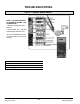

A. O. Smith Water Products Company Service Handbook
Irving, Texas 2000
©
Training Department
27
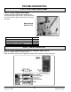
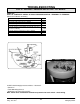
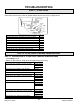
STEP 10. CONTINUITY CHECK OF EACH PRESSURE SWITCH - TERMINAL TO TERMINAL.
(Meter buzz indicates continuity)
IF… THEN
Block inlet switch does not show continuity replace
Block inlet switch does show continuity continu
e
Blower proving switch does not show continuity continu
e
Blower proving switch does show continuity replace
Low gas pressure switch does show continuity continu
e
Blocked outlet pressure switch does not show continuity replace
Blocked outlet pressure switch does show continuity continu
e
Low gas pressure switch (BTH 120 and 250 only) does
not show continuity
chec
k
repla
c
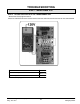
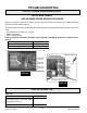
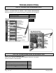
24 VAC check through pressure switches – blower off.
• Power on
• Tank not calling for heat
• Multimeter set to check for 24 VAC
Note: Power flows from bottom terminal to top terminal of each switch – check wiring
STEP 10 - CONTINUITY PRESSURE SWITCH TEST - ALL MODELS
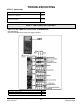
TROUBLESHOOTING
Power Off