MODELS BTP(V)-540A, 650A AND 740A COMMERCIAL GAS, GLASS-LINED, TANK-TYPE LOW NOx WATER HEATER • INSTALLATION • OPERATION • MAINTENANCE • LIMITED WARRANTY CONSER VATIONIST ® CONSERV CAUTION TEXT PRINTED OR OUTLINED IN RED CONTAINS INFORMATION RELATIVE TO YOUR SAFETY. PLEASE READ THOROUGHLY BEFORE INSTALLING AND USING THIS APPLIANCE. A DIVISION OF A.O.SMITH CORPORATION MCBEE, SOUTH CAROLINA www.aosmithwaterheaters.
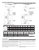
ROUGH-IN DIMENSIONS HORIZONTAL & DIRECT VENTING BTPV MODELS STANDARD BAROMETRIC DRAFT CONTROL BTP MODELS MAXIMUM TOTAL 75 EQUIVALENT FEET INTAKE AND EXHAUST ALLOWED.
In the absence of local codes, the installation must conform with the instructions as outlined in the latest publication of National Fuel Gas Code (NFPA-54/ANSI Z223.1) and National Electric Code (NFPA-70). These manuals can be purchased from the Canadian Standards Association Laboratories, 8501 East Pleasant Valley Road, Cleveland, OH 44131, National Fire Protection Association, 1 Batterymarch Park, Quincy MA 02269.
and sodium chloride (water softener salt), waxes, and process chemicals are typical compounds which are potentially corrosive. Do not store products of this sort near the heater. Also, air which is brought in contact with the heater should no contain any of these chemicals. If necessary, uncontaminated air should be obtained from remote or outside sources. The limited warranty is voided when failure of water heater is due to a corrosive atmosphere.
LOCATING THE HEATER Continued manual resetting of high limit control, preceded by higher than usual water temperature is evidence of high limit switch operation. The following are possible reasons for high limit switch operation. When installing the heater, consideration must be given to proper location. Location selected should be as close to the stack chimney as practicable, with adequate air supply and as centralized with the piping system as possible.
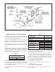
Units, which are to be installed on combustible flooring, must be supported by a full layer of hollow concrete blocks, from 8” (203.2 mm) to 12” (304.8 mm) thick and extending 12” (304.8 mm) minimum beyond the heater in all directions. The concrete blocks must provide an unbroken concrete surface under the heater with the hollows running continuously and horizontally. A 3/16-inch steel plate must cover the concrete blocks, see Figure 2.
NOTE: A NEGATIVE DRAFT MUST BE MAINTAINED IN VENTING. Heater must be protected from freezing downdrafts during shutdown periods. A negative draft of 0.02” to 0.04” w.c. Must be maintained in venting system. Measure draft at the location illustrated in Figure 4. Adjust the control counter-weights if necessary as shown in the MAINTENANCE portion of this manual.
5. Shall not be closer than 3 feet (0.9 m) from the inside corner of an L- shaped structure. Refer to Table 2 for limitations of venting system design for horizontal venting. TABLE 2 6. Shall be located above the snow line in geographical areas where snow accumulates. BTPV-540A-740A Flue Outlet Dia. (Inches/mm) Flue Reducer Dimensions -Supplied (Inches/mm) Minimum Outlet Vent Dia. (Inches/mm) Maximum Number 90° Of Elbows 45° Maximum Total Vent System Length, Equiv. Feet/Meters 9” (228.6) 9” x 8” 228.
FIGURE 6. DIRECT VENTING - FOR BTPV MODELS TABLE 5. All exhaust vent terminal, flue reducer, and intake vent terminal are supplied with any unit intended for direct venting. These parts must be installed without alteration. This heater is category III appliance when used in a direct vent application. All national and local codes pertaining to the installation of such an appliance must be followed. Horizontal portions of the exhaust vent system must be installed with a minimum upward slope of 1/4” (6.
1. Shall be located not less than 12” (304.8 mm) above grade. DIRECT VENT SYSTEM INSTALLATION 2. Shall be located not less than 3 (.9144 m) feet horizontally from and not less than 3 feet (.9144 m) below an exhaust vent terminal. Plan the vent system backwards from the vent hood to the heater. 1. Use the inside wall cover plate as a template to mark two holes in the appropriate places on the wall. Cut holes 1/2” (12.7 mm) larger to facilitate easy installation of vent hoods, see Figures 6 and 7. 3.
5. 6. Attach a properly sized length of Selkirk Metalbestos model PS or model G venting to the exhaust vent adapter using the inner vee bands, see Figures 7 and 7B on page 10. WARNING PRIMERS AND CEMENTS ARE EXTREMELY FLAMMABLE, AND MUST NOT BE STORED OR USED NEAR HEAT OR OPEN FLAME. ALLOW ADEQUATE CURING TIME BEFORE OPERATING HEATER. Fill the grooves in both inner vee bands with high-temp silicone sealant, Dow Corning 736 or equivalent. 7.
TABLE 9A ANY SUPPLY PRESSURE TESTING EXCEEDING 1/2 PSIG. GAS SUPPLY LINE MUST BE CAPPED WHEN DISCONNECTED FROM THE HEATER. FOR TEST PRESSURES OF ½ PSIG OR LESS, THE APPLIANCE NEED NOT BE DISCONNECTED, BUT MUST BE ISOLATED FROM THE SUPPLY PRESSURE TEST BY CLOSING THE MANUAL GAS SHUT-OFF VALVE. MAXIMUM CAPACITY OF PIPE IN CUBIC FEET OF GAS PER HOUR (Based upon a Pressure Drop of 0.5 inch Water Column and 0.5 Specific Gravity Gas and max. gas press. of .5 psig) LENGTH IN METERS 1/2" 3.0 51 6.1 35 9.1 28 12.
to the local code authority having jurisdiction. Good practice requires that all heavy piping be supported. THERMOMETERS (Not supplied) Thermometers should be obtained and field installed as shown in the installation diagrams. Thermometers are installed in the system as a means of detecting the temperature of the outlet water supply. RELIEF VALVE ROBERTSHAW 7000 DERHC GAS CONTROL VALVE FIGURE 10. This heater is equipped with an approved temperature and pressure relief valve.
INSTALLATION DIAGRAMS ONE TEMPERATURE - ONE HEATER VERTICAL STORAGE TANK FORCED CIRCULATION WITH OR WITHOUT BUILDING RECIRCULATION DANGER IF BUILDING COLD WATER SUPPLY HAS A BACKFLOW PREVENTER, CHECK VALVE OR WATER METER WITH CHECK VALVE, PROVISIONS FOR THERMAL EXPANSION OF WATER IN THE HOT WATER SYSTEM MUST BE PROVIDED. NOTE: CONNECT RETURN LINE FROM HOT WATER RECIRCULATING LOOP (IF USED) TO COLD WATER INLET LINE. NOTE: WHEN USING AN A.O.
TWO TEMPERATURE - ONE HEATER HIGH TEMPERATURE WITH OR WITHOUT BUILDING RECIRCULATION *PIPE RELIEF VALVE TO OPEN DRAIN NOTE: IF TEMPERED WATER IS RECIRCULATED, RETURN LINE SHOULD BE CONNECTED AT POINT “A”. INSTALL IN ACCORDANCE WITH LOCAL CODES DANGER TEMPERATURE SETTING SHOULD NOT EXCEED SAFE TEMPERATURE AT FIXTURES. SEE WATER TEMPERATURE CONTROL WARNING ON PAGE 23. IF HIGHER PREHEAT TEMPERATURES ARE NECESSARY TO OBTAIN ADEQUATE BOOSTER OUTPUT, ADD AN ANTI-SCALD VALVE FOR HOT WATER SUPPLIED TO FIXTURES.
TWO TEMPERATURE - THREE HEATERS (TWO PRE-HEATERS/ONE BOOSTER) WITH OR WITHOUT BUILDING RECIRCULATION CAUTION: IF BUILDING COLD WATER SUPPLY HAS A BACKFLOW PREVENTER, CHECK VALVE OR WATER METER WITH CHECK VALVE, PROVISIONS FOR THERMAL EXPANSION OF WATER IN THE HOT WATER SYSTEM MUST BE PROVIDED. FOR MULTIPLE HEATER INSTALLATION SEE MANIFOLD KIT SPECIFICATIONS, PAGE 18. DANGER TEMPERATURE SETTING SHOULD NOT EXCEED SAFE TEMPERATURE AT FIXTURES. SEE WATER TEMPERATURE CONTROL WARNING ON PAGE 23.
TWO TEMPERATURE - ONE HEATER HIGH TEMPERATURE WITH RECIRCULATION OF SANITIZING LOOP DANGER TEMPERATURE SETTING SHOULD NOT EXCEED SAFE TEMPERATURE AT FIXTURES. SEE WATER TEMPERATURE CONTROL WARNING ON PAGE 23. IF HIGHER PREHEAT TEMPERATURES ARE NECESSARY TO OBTAIN ADEQUATE BOOSTER OUTPUT, ADD AN ANTI-SCALD VALVE FOR HOT WATER SUPPLIED TO FIXTURES.
TWO UNIT MANIFOLD KIT PART NO. 195702 MANIFOLD KITS Precision cut type “L” all copper A. O. Smith manifold kits assure water flow balance of all units. Without this balance, the full water heating and storage potential of the system cannot be achieved. Plus, the units with the higher water flow may have a shortened life. Unions shown in piping diagrams are not included in the manifold kits. Dimensions shown are for minimum space occupied by the water heaters assemblies.
2. Open a nearby hot water faucet to permit the air in the system to escape. HEATER WIRING IF ANY OF THE ORIGINAL WIRE AS SUPPLIED WITH THE APPLIANCE MUST BE REPLACED, IT MUST BE REPLACED WITH 105°C WIRE OR ITS EQUIVALENT, EXCEPT IN THE BURNER HOUSING USE 200°C WIRE. 3. Fully open the cold water inlet pipe valve allowing the heater and piping to be filled. 4. Close the hot water faucet as water starts to flow. 5. The heater is ready to be operated.
FIGURE 11.
FIGURE 12.
FOR YOUR SAFETY READ BEFORE LIGHTING WARNING: If you do not follow these instructions exactly, a fire or explosion may result causing property damage, personal injury or loss of life. BEFORE OPERATING: ENTIRE SYSTEM MUST BE FILLED WITH WATER AND AIR PURGED FROM ALL LINES. • If you cannot reach your gas supplier, call the fire A. This appliance is equipped with an ignition device which department. automatically lights the burner. Do NOT try to light burner by hand. C.
SEQUENCE OF OPERATION – – – – – – – – – – – – – – DANGER Power on. Heater in standby mode. Thermostat calls for heat. Blower motor starts. Blower operation closes the normally open blower prover/ blocked outlet safety pressure switch. On proof of airflow, Honeywell S8680J flame control module energized. 45 seconds prepurge cycle begins. Following prepurge cycle, the pilot gas valve is energized. At the same time, the electronic spark generator in the module produces a high voltage spark pulse output.
1. Check gas line pressure with a manometer. it’s a high elevation application and/or a direct vent (long air intake vent) application. Set initial gas line pressure at 9-10” w.c. before turning the heater “ON”. 1. Fire Rate Adjustment (including direct vent installation). Read gas line pressure and gas manifold pressure when the heater main gas is “ON”. a. Make sure the gas supply line pressure reads 8” w.c. (2 kPa) or higher when the heater is running.
PREMIX LOW NOx BURNER - EXPLODED VIEW FOR BTP MODELS FIGURE 13.
PREMIX LOW NOx BURNER - EXPLODED VIEW FOR BTPV MODELS FIGURE 14.
to the following table. A periodic inspection of the venting system should be made. Where used the water heating system circulating pump should be oiled. GENERAL INFORMATION POWER BURNER MAINTENANCE SCHEDULE The initial start-up procedure of the gas power burner is provided on page 18 thru 21. Refer to Figure 12, burner exploded view for burner components location. Following are the instructions for performing some of the recommended maintenance.
DRAINING A.O. Smith UN•LIME® Delimer is an easy to handle patented food grade acid formulated specifically for lime scale removal from all types of water using equipment. Available in 1 gallon (part no. 4763) and 5 gallon (part no. 4813) sizes. Hydrochloric base acids are not recommended for use on glass-lined tanks. The heater must be drained if it is to be shut down and exposed to freezing temperatures. Maintenance and service procedures may also require draining the heater. 1.
ABOVE ALL, DO NOT PLUG THE TEMPERATURE AND PRESSURE RELIEF VALVE. THIS IS NOT A SOLUTION AND CAN CREATE A HAZARDOUS SITUATION. CIRCULATING PUMP The water heating system may include a circulating pump. Where used, it should be lubricated as directed by the circulator manufacturer. LOW EMISSION POWER BURNER FIGURE 15 KEEP THE AREA AROUND THE BURNER CLEAR AND FREE OF COMBUSTIBLE MATERIALS, GASOLINE OR OTHER FLAMMABLE LIQUIDS OR VAPORS.
2. Check the fuses. • Excessive water pressure • The electrical disconnect switch usually contains fuses. 3. The capacity of the heater may have been exceeded by a large demand for hot water. 4. Colder incoming water temperature will lengthen the time required to heat water to the desired temperature. • If the heater was installed when incoming water temperature was warm, colder water creates the effect of less hot water. 5. Look for hot water wastage and leaking or open hot water faucets. 6.
Refer to the SEQUENCE OF OPERATION and burner exploded view, see Figure 12 and the wiring diagram located on page 20, and the troubleshooting section of burner manual before continuing. Make sure the appliance is connected to a 120 Vac power supply, burner switch is “ON” and manual gas valve is in the “ON” position, and all electrical connections are secure before continuing to troubleshoot this appliance. • Check for the low gas pressure switch by ohm meter (while pilot gas pressure is 7” w.c. [1.
• Do not proceed to Step 5 unless 24V is detected at “24V” terminal of the Honeywell Module. 1. Make sure main manual gas valve (right after the Robertshaw gas valve) is fully open; 5. As soon as the pilot gas valve is energized, check for the burner pilot flame through the burner peek-hole. If the pilot flame is established inside the burner, then proceed to Step 6. 2. Check for 24V at the Robertshaw gas valve when the main gas light is on. If there’s no 24V at the valve, check loose wire connection. 3.
Model BTP(V) Limited Warranty A.O. Smith Corporation, the warrantor, extends the following LIMITED WARRANTY to the owner of this water heater. 1. THE TANK If the glass-lined tank in this water heater shall prove upon examination by the warrantor to have leaked due to the natural corrosion from potable water therein, during the first THREE years after installation, the warrantor will supply a complete new A.O. Smith water heater of equivalent size and current model.
NOTES 34
NOTES 35
REPLACEMENT PARTS 5621 W. 115TH STREET, ALSIP, IL 60803 Phone: 800-433-2545 Fax: 800-433-2515 www.aosmithwaterheaters.com E-Mail: parts@hotwater.