
Installation Guide


18 • Residen al Electric Water Heater Use and Care Guide
INSTALLATION
18 • Residen al Electric Water Heater Use and Care Guide
INSTALLATION
The Electronic Thermostat
IMPORTANT: The Energy Smart
®
Module
(ESM) must be removed before a empt-
ing to access the thermostat. NOTE: for
the Electronic Thermostat (ET) changes
to remain in eff ect the Energy Smart
®
Module (ESM) must not be reconnected,
also read the “Water Temperature Regu-
la on” under the “Opera ng Your Water
Heater” sec on. If the instruc ons are
not clear, contact a qualifi ed service
technician.
The Energy Smart
®
Module (ESM) is in-
tended to serve as the primary interface
for opera ng the water heater; however,
the Electronic Thermostat (ET) may
control the water heater in the absence
of the Energy Smart
®
Module (ESM).
The Electronic Thermostat consists of
an electronics box that contains a low
voltage power supply, the thermostat
set point knob, relays to switch between
the upper and lower hea ng elements,
one control thermistor, a connector for
the lower element control thermistor,
microelectronics to convert the thermis-
tor signals and perform switching and
other logic func ons, and a connector to
e the Electronic Thermostat (ET) to the
Energy Smart
®
Module (ESM) located
on the front of the water heater jacket.
The majority of the self-diagnos cs are
located in the Electronic Thermostat
(ET), including the dry-fi re protec on
intelligence. The thermostat circuit is
designed so that when the upper heat-
ing element calls for heat, the power
is directed to that element even if the
lower element is also calling for heat.
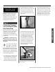
Diagnos c LED Light
The Green/Red LED light indicates the
status of the electronic thermostat (See
Figure 9).
• Green LED will signal normal opera-
on. The green LED will blink 2 mes
per second to indicate that power is ap-
plied to the upper hea ng element and
at a faster rate (4 mes per second) to
indicate that the lower hea ng element
is powered.
• Red LED will fl ash error codes. If
a fault is detected by the electronic
thermostat, the LED light indicator will
use the red LED to indicate the fault
detected. The fl ash code sequence is to
consist of 1/2 second fl ashes of the red
LED each separated by a 1/2 second off
period.
The number of fl ashes indicates the
fault code number.
(See diagnos c code chart sec on in
this manual).
A er the last 1/2 second “on” period,
the LED will remain off un l a total of 5
seconds has elapsed for the fault indica-
on cycle (there is a 5 seconds delay
before the fault fl ash pa ern repeats).
A er the 5 seconds are completed, the
fault indica on cycle is repeated star ng
with the fi rst 1/2 second-fl ash. The fl ash
sequence will be repeated as long as
the fault remains. Only one fault can
be declared at a me. NOTE: the green
LED is turned off when a fault code is
being displayed, even though the heater
may be opera ng in limp mode with an
element on. See diagnos c code chart
sec on in this manual.
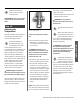
Overriding The Energy
Smart
®
Module (ESM)
If the Energy Smart® Module (ESM) is
not working, simply unplug the inter-
face module and turn the set point knob
on the Electronic Thermostat (ET) to the
desired temperature (See Figures 9 &
10). To replace a broken or damaged
ESM module, see page 36 for ordering
informa on.
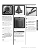
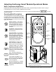
Figure 9
Electronic Thermostat (ET)
Diagnostic
LED Light
ECO Reset
Button
Setpoint
Knob
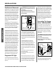
Remove Only After Power Is
Turned O When Replacing Element.
Plastic Guard
Upper
Element
Electronic Thermostat (ET)
NOTE: Smart Grid will be disabled when the
Energy Smart®
Module (ESM) is disconnected
from the junc on box wiring harness.
Energy Smart®
Module (ESM)
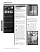
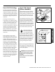
Figure 10
Electronic
Thermostat (ET)
Thermostat
Setpoint Knob
Junction Box
Wiring Harness
Thermistor
Wire Harness
WARNING! Electrical Shock Hazard
Do not remove the plas c guard from
over wiring.
Do not touch electrical wiring.
Failure to do so can result in death or
electrical shock.
WARNING! Electrical Shock Hazard
Do not remove the plas c guard from
over wiring.
Do not touch electrical wiring.
Failure to do so can result in death or
electrical shock.