
Installation Guide


29
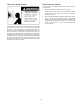
REMOVING THE BURNER FROM THE
MANIFOLD/BURNER ASSEMBLY
1. Take off the burner by removing the two (2) screws located
underneath the burner.
2. Check the burner to see if it is dirty or clogged. The burner
may be cleaned with soap and hot water (Figure 41).
BURNER
(BOTTOM VIEW)
SCREWS
PILOT ASSEMBLY
(BOTTOM VIEW)
NOTE: SCOOP NOT PRESENT
ON SOME MODELS
FIGURE 38.
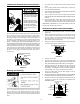
REPLACING THE PILOT/ THERMOCOUPLE
ASSEMBLY
1. Remove the manifold door assembly as described in “Removing
the Manifold/Burner Assembly” section.
2. Remove the burner to access the pilot/thermocouple assembly.
Remove and keep the screws securing the burner to the
manifold (Figure 41). IMPORTANT: DO NOT remove the orifice.
3. Remove the screw securing the pilot/thermocouple assembly to
the pilot bracket and keep for reuse later (Figure 42).
4. Lift the retainer clip straight up from the back of the manifold
component block (using a fl at-blade screwdriver), then remove
the manifold component block from the manifold door (Figure 42).
IMPORTANT: Be careful not to bend or alter the position of the
pilot tube. It will be used as a bending template for the new pilot
assembly. Note the placement/order of the wires in the manifold
component block.
5. Lift the pilot/thermocouple assembly (including the igniter wire)
from the manifold assembly.
OTHER FITTINGS
NOT SHOWN
FOR CLARITY
IGNITER WIRE
THERMOCOUPLE
TWO PIECE
WIRE CONNECTOR
RETAINER
CLIP
PILOT TUBE
PILOT BRACKET
PILOT
MANIFOLD TUBE
MANIFOLD/BURNER
DOOR OPENING
FERRULE NUT
FIGURE 39.
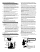
6. Read this step carefully before proceeding. Using the old pilot/
pilot tube assembly as a guide, bend the new pilot tube to match
the old one. Make only the bends closest to the pilot before going
to the next step.
FIRST BEND(S)
OTHER FITTINGS
NOT SHOWN
FOR CLARITY
PILOT TUBE
THERMOCOUPLE
IGNITER WIRE
SCREW
OLD PILOT ASSEMBLY
FIGURE 40.
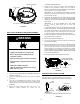
7. Route the new pilot tube and wires through the opening in the
manifold door. See Figure 41.
8. Using the pilot screw removed earlier, attach the new pilot/
thermocouple assembly. Reattach the burner to the manifold
using the screws removed earlier. NOTE: If the burner has a
scoop, make sure that the scoop is oriented to the pilot side of
the manifold tube (Figure 41).
9. Reinstall the manifold component block in the manifold door.
Ensure that the pilot tube and wires are positioned as shown in
Figure 44.
10. Carefully bend the new pilot tube to match the bend of the
manifold tube. NOTE: When bending, DO NOT crimp or crease
the pilot tube.
11. Before you proceed to the next step, install the new brass ferrule
nut in the gas control valve/thermostat’s pilot tube opening, HAND
TIGHT ONLY.
12. Install the manifold/burner assembly. Refer to the “Replacing
the Manifold/Burner Assembly” section for instructions.
TWO PIECE WIRE CONNECTOR
PILOT TUBE
IGNITER WIRE
THERMOCOUPLE
FIGURE 41.
C L E A N I N G T H E C O M B U S T I O N C H A M B E R
1. Follow procedure outlined in “Removing the Manifold/Burner
Assembly”.
2. Use a vacuum cleaner/shop vac to remove all loose debris in
the combustion chamber (Figure 45).
3. Reassemble following the procedure under “Replacing the
Manifold/Burner Assembly.”