
Instruction manual


23
IRI Gas Valve Sensor:
• IRI Gas Valve (CCB - optional):
Normally open switch that closes when the IRI Gas Valve is
operating correctly. This input is enabled/disabled by a
dipswitch on the CCB.
• Flame Sensor:
Flame (CCB - required).
Returns a signal to the microprocessor if flame is detected in
the burner. If the probe is missing or shorted, the flame will
not be detected. This input is enabled/disabled by a dipswitch
on the FCB.
Outputs from CCB and FCB's:
Relay Contact Output:
• IRI Gas Valve (CCB - 120 vac - optional):
Provides electrical power to operate an IRI Gas Valve Device.
• Alarm (CCB - 24vac - optional):
Provides electrical power to operate an external alarm. This
can be an audio device (i.e. Sonalert), a visual device (lamp),
or any other device that will operate with the voltage and current
level provided.
• Pump (CCB - 120vac - required on systems that do not have
an external pump):
Provides electrical power to directly operate a pump or the
coil of an externally connected contactor.
• Powered Vent (CCB - 24 vac - optional):
Provides electrical power to operate a powered vent.
• Blower (CCB / FCB - 120vac - required).
Single speed blowers utilize the high blower output only. Dip
switches on the FCB's enable/disable the use of blowers on
stages 2, 3 and 4.
• Igniter (FCB - 120vac - required).
Provides power to operate the HSI igniters. Dip switches on
the FCB's enables/disables the use of HSI igniters on stages
2, 3 and 4.
• Gas Valve (FCB - 24vac - required):
Provides power to activate the gas valve. The gas valve cannot
be activated when the ECO contacts are open
Direct Connection Output:
• Low Water Cut Off (CCB - 24vac - optional)
Directly connected to the 24 vac line to provide power to operate
an external LW/CO device.
CCB/FCB Indicator Lamps & Fuses
A green LED is mounted on the PDB to indicate when line voltage
is applied. (The CCB/FCB/PDB also contain a yellow, green, red
LED, and a test/run jumper, that are used during installation to
verify proper power connections.) A red LED on the CCB is used
to indicate when the 24vac input fuse has blown. The FCB's also
have fuses on their 24vac power line. (Recommended
replacement fuses are: Littlefuse p/n 29707.5 for the 7.5 amp
CCB fuse, and Littlefuse p/n 297003 for the 3 amp FCB fuses.)
Repeated failure of a fuse is an indication of failure in some
part of the system.
Yellow LED's are located near the micros on the CCB and FCB's.
These LED's are "heartbeat indicators" and blink approximately
twice per second to indicate that the micros are running. (The
blink rate of the LED next to the micro that controls the silicon
Nitride igniter will change when the igniter is being powered and
when a fault is detected with the operation of that igniter.)
CCB/FCB Jumpers:
The CCB has two jumpers and the FCB has one. JP1 on the
CCB is used to terminate the external communications line. It is
normally left off and installed when the external cable is very
long. JP2 on the CCB and JP1 on the FCB, are for factory use
only.
Igniters
The EMC 5000 system operates with Silicon Carbide Igniter.
CCB/FCB Dip Switches:
Dipswitch configurations are
READ ONLY ON POWER UP. These switches are only to be set at the factory or by authorized-trained
personnel only! Once set at installation they generally remain that way for the duration of the life of the product. If a switch is changed,
power must be cycled before the change will take effect. The status of all dipswitches can be observed on the system status screen
on the UIM.
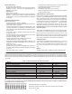
CCB - Ten Position Dipswitch (Central Control Board)
SWITCH
Switch 1: Selection of the type of boiler application: On = GB/LB Off = GW/LW
Switch 2: Trials for Ignition: On = 3 Off = 1
Switch 3: IRI Gas Valve Option: On = IRI Off = No IRI
Switch 4: Controlling Probe: On = Tank Off = Inlet
Switch 5: Powered Vent: On = Yes Off = No
Switch 6: Low Water Cut Off: On = Yes Off = No
Switch 7: Low Gas On = Yes Off = No
Switch 8: Spare:
Switch 9 & 10. Number Stages (FCB's): 9 10 #stages
Off On = 2
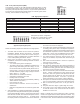
NOTE: If the unit power up with the number of stages selected by dip switches exceeding the number of FCBs, the CCB will detect
this condition and go into a hard lockout. After changing the dip switches to the correct number of stages, the power must be
cycled off and on to accept the change.
Example of Dip Switch configuration:
GW model, 1 ignition trial, No IRI, Inlet control, No Power Vent, No LWCO,
No Low Gas, 2 stage.