
Instruction manual


37
• System control (tank probe, thermostat, etc.) is calling for
appliance operation (call for heat).
• Other contacts (switches) are closed (low water cutoff, flow
switch, limit controls, pressure switches, etc.)
• Gas supply pressure is within the maximum and minimum
operating ranges listed on the appliance rating plate/label.
• Appliance is wired according to wiring diagram.
NOTE: Shorting the thermostat wiring to ground in the 24 volt
circuit will blow the 3 amp fuse.
• All wire terminals/connectors are firmly attached to valves,
modules, switches, limit controls, etc.
• There has been no damage caused by freezing, inoperative
pumps, etc.
DESCRIPTION OF COMPONENTS
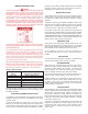
DIFFERENTIAL PRESSURE SWITCH
The differential pressure switch ensures that a sufficient
differential exists between the air pressure in the pre-mix chamber
and the inlet of the burner for safe, low NOx combustion. The
switch has two pressure taps marked "+" (positive) and "-"
(negative). Silicone tubing is run from the positive pressure tap
of the switch to a tap on the control panel to measure the air
pressure in the pre-mix chamber. The negative pressure tap
measures the pressure taken at the burner's auxiliary tube.
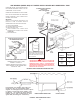
Connections can be seen by removing the lower front jacket
panel. It is important that this panel remain sealed at all times
while the boiler is operating.
BLOCKED FLUE PRESSURE SWITCH
The blocked flue pressure switch ensures that the flue gas vent
is clear. This pressure switch is normally closed and only opens
on the fault conditions.
FLAME SENSOR
The flame sensor acts to prove the flame has carried over from
the ignitor to the right-most burner of stage 1. If no flame is
sensed, the gas valve(s) will close automatically. And If no flame
is sensed on three (or one) ignition trials the boiler will lock out.
Upon lockout, manually push the SELECT button on the UIM to
restart the boiler.
WATER FLOW SWITCH
The Water Flow Switch is installed at the boiler outlet to prevent
burner operation in the event of inadequate water flow through
the boiler. The Water Flow Switch is a single pole, normally open
switch that will close its contacts when increasing water flow
rate is encountered. This switch is factory-set, but may require
field adjustment. The contacts will open when the flow rate drops
below the adjusted setting and the gas valve(s) will close turning
off the gas to the burners.
LIMIT CONTROLS
This boiler contains two limit controls built into the outlet water
probe. The automatic reset limit is adjustable from 90°F to 235°F.
The manual reset limit is factory-set at 250°F. Once the manually
reset limit opens, the gas valve(s) will close and the boiler will
lockout. Upon lockout, manually push the SELECT push-button
on the UIM to restart the boiler.
ON/OFF SWITCH
The ON/OFF switch is a single-pole, single-throw rocker switch.
The switch provides 120VAC from the line source to the boiler.
COMBUSTION AIR BLOWER
The bearings in the motor are pre-lubricated and sealed at the
factory. No further oiling of the bearings is required for the life of
the motor.
GENERAL MAINTENANCE
These boilers are designed to give many years of efficient
and satisfactory service when properly operated and
maintained. To assure continued good performance, the
following recommendations are made.
The area around the unit should be kept clean and free from lint
and debris. Sweeping the floor around the boiler should be
done carefully. This will reduce the dust and dirt which may enter
the burner and heat exchanger, causing improper combustion
and sooting.
THE FLOW OF COMBUSTION AIR TO THE BOILER MUST NOT BE
OBSTRUCTED.
THE BOILER AREA MUST BE KEPT CLEAR AND FREE FROM
COMBUSTIBLE MATERIALS, GASOLINE AND OTHER
FLAMMABLE VAPORS AND LIQUIDS.
Any safety devices including low water cutoffs used in conjunction
with this boiler should receive periodic (every six months)
inspection to assure proper operation. A low water cutoff device
of the float type should be flushed every six months.
Periodic checks, at least twice a year, should be made for water
and/or gas leaks.
More frequent inspections may be necessary depending on water
conditions.
The boiler-mounted gas and electrical controls have been
designed to give both dependable service and long life. However,
malfunction can occur, as with any piece of equipment. It is
therefore recommended that all components be checked
periodically by a qualified serviceman for proper operation.
RELIEF VALVE
The safety relief valve should be opened at least twice a year to
check its working condition. This will aid in assuring proper
pressure relief protection. Lift the lever at the top of the valve
several times until the valve seats properly and operates freely.
DANGER
THE WATER PASSING OUT OF THE VALVE DURING CHECKING
OPERATION MAY BE EXTREMELY HOT. BEFORE OPERATING
RELIEF VALVE, MAKE SURE DRAIN LINE IS INSTALLED TO DIRECT
DISCHARGE TO A SAFE LOCATION SUCH AS AN OPEN DRAIN,
TO AVOID SCALDING OR WATER DAMAGE.