
Instruction manual


39
Before starting the boiler please review the Boiler’s Instruction Manual (AOS Part Number 212130-002) supplied with the
boiler. This is a powered combustion copper tube boiler. If you are not familiar with a powered combustion boiler please
contact an authorized A.O. Smith representative before starting the unit.
This boiler is equipped with an EMC5000 control system. The EMC5000 displays the system status and errors that may
occur during normal operation. For full details on the controls please refer to the Instruction Manual supplied with the boiler.
The boiler must be installed according to the Installation Instructions provided with the unit. Failure to do so will void the
warranty.
Prior to starting the boiler for the first time check the following:
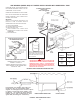
Before applying gas or water to the system, the power line electrical hook-up can be verified. If connected, remove the plug
in connectors (J1, J2, J3) on the Power Distribution Board (PDB) and place the jumper (JP1) on the PDB in the “Test” position.
(Note: Leaving the connectors connected during this test will product invalid light indications that will not match the table.)
Apply electrical power to the system and observe the three colored LED’s on the PDB. Verify that the proper light turns on
according to the following table:
When connections are correct, turn off power, move jumper to “Run” position, and reconnect cables to PDB.
(Note: With the jumper in the “Run” position, only the Green LED functions.)
Prior to turning on the gas, proper operation of much of the system can be verified. With the water turned on, start
the system and allow it to run through a heating cycle. It should stop when it checks for flame and declare a fault.
This will verify that the pump, flow switch, igniter, gas valve, blower and blower differential pressure switch are
all functioning.
Gas Supply Lines are sized in accordance with ANSI Z223.1 National Fuel Gas Code or CAN/CSA-B149.1
(current edition).
Minimum Inlet Gas Supply Pressure of 5.5” W.C. for Natural Gas or 11.0” W.C. for Propane.
Check all gas supply lines for leaks.
Check that all venting is properly sealed in accordance with the Instruction Manual.
Main power is dedicated 120 VAC, 60Hz, single phase, rated for 20 Amps.
Turn “ON” gas and water supply to the boiler ( DO NOT DRY FIRE THE BOILER ).
Purge air from the gas and water lines.
Make sure the boiler is not damaged. If the unit is damaged contact an A.O. Smith representative for service or replacement
parts prior to starting the boiler.
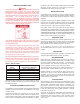
COPPER BOILERS FOR HYDRONIC HEATING AND HOT WATER SUPPLY
SERIES 400, 401,402, 403, 404, 405, 2-Stage Units
Start-up Instructions
PLACE THESE INSTRUCTIONS ADJACENT TO BOILER AND NOTIFY OWNER TO KEEP FOR FUTURE REFERENCE.
Line Connection Status Green LED Red LED Yellow LED
Proper connections (On) Off (On)
Open Ground Off (On) Off
Reverse Polarity (On) (On) Off
Open Hot Off Off Off
Open Neutral (On) (On) (On)
Reverse Hot & Ground Off (On) (On)
Hot on Neutral with Hot Open Off (On) Off