
Manual

INSTALLATION AND MAINTENANCE MANUAL
ODOR CONTROL FILTER ASSEMBLY
DESCRIPTION
e Odor Control assembled unit can be installed on a number of A.R.I. combination air valves
for wastewater.
e unit absorbs the noxious odors emitted from a wastewater system, which are a nuisance both
in the residential as well as in the work environment.
e odor control lter assembly can be installed on A.R.I. wastewater air valve models D-020,
D-025, D-023.
e unit is both portable and disposable.
No heavy equipment is needed and there is no messy disposal of spent carbon.
SIZES
MAINTENANCE
Filter Model 1214 1620 1630
Maximal Flow Capacity 200/350 m
3
h 420/713 m
3
h 600/1000 m
3
h
Outlet 2” 2” 2”
Dimensions 30x32.5 cm 41.25x49.25 cm 41.25x73.75 cm
Weight 7 Kg. 18 Kg. 27 Kg.
e life expectancy of the odor lter cartridge is dependent upon certain parameters, including: the ow rate of the discharged gas, humidity and
the organic substance concentration. Our recommendation is to replace the cartridge at least once a year or if noxious odors start to emanate from
the cartridge.
See instructions for replacing the odor lter cartridge (found below after the Assembly Instructions).
INSTALLATION OF ODOR CONTROL FILTER ASSEMBLY
Important: e Odor Control Filter Assembly can only be connected to a D-020, D-025 A.R.I. Wastewater Valve which has a male quick
connector assembled in the discharge outlet. If not, please call a A.R.I. service representative to obtain the correct parts.
e Odor Control Filter Assembly is shipped fully assembled and ready to be attached to the A.R.I. wastewater air valve models D-020, D-025,
D-023.
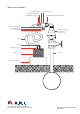
1. Attach the quick connector end (3) of the Odor Control Filter Assembly to the cam lock type quick connector (2) on the
wastewater air valve.
2. Securely close the two fasteners on the quick connector (3).
NOTE: The unconnected side of the “T” connection containing the one-way out check valve (4) must be unobstructed and
able to freely intake air. The “T” connection can be rotated to insure the check valve has unobstructed clearance.
3. Place a concrete support block (10) or any other type of level support block (at least 20 cm in height) on the ground
next to the wastewater valve.
NOTE: Make certain that there are no kinks in the tubing and the lter cartridge is above the water level in case of ooding
in the manhole.
4. Stand the Odor Control Filter Assembly unit (9) level on the support block.
The unit is now connected and installed and will operate automatically.
REPLACING THE FILTER CARTRIDGE
1. Unfasten the fasteners of the quick connector (7) and detach from the threaded quick connector (8).
2. Unscrew and remove the threaded quick connector (8) from the top of the Odor Control Filter Assembly lter unit (9).
3. Remove the Odor Control Filter Assembly lter unit from the support block and place it in a leak proof strong disposable bag.
Dispose of the unit according to local environmental regulations.
5. Stand the new Odor Control Filter Assembly lter unit (9) level on the support block.
6. Screw the threaded quick connector (8) into the top of the new Odor Control Filter Assembly lter unit (9).
7. Attach the end of the quick connector (7) to the end of the threaded quick connector (8) and close the two fasteners securely.