Touch Panel PC AHP-2176 AHP-2176 Onboard Intel® Celeron® 827E 1.4GHz Processor Touch Panel PC With 17” TFT LCD AHP-2176 Manual 3rd Ed.
Touch Panel PC AHP-2176 Copyright Notice This document is copyrighted, 2014. All rights are reserved. The original manufacturer reserves the right to make improvements to the products described in this manual at any time without notice. No part of this manual may be reproduced, copied, translated, or transmitted in any form or by any means without the prior written permission of the original manufacturer. Information provided in this manual is intended to be accurate and reliable.
Touch Panel PC AHP-2176 Acknowledgments All other products’ name or trademarks are properties of their respective owners. AMI is a trademark of American Megatrends Inc. Intel , and Atom™ are trademarks of Intel Corporation. Microsoft Windows is a registered trademark of Microsoft Corp. IBM, PC/AT, PS/2, and VGA are trademarks of International Business Machines Corporation. ® ® ® All other product names or trademarks are properties of their respective owners.
Touch Panel PC AHP-2176 Packing List Before you begin operating your PC, please make sure that the following materials are enclosed: AHP-2176 Touch Panel PC Mounting brackets and screws DVD-ROM for manual (in PDF format) and drivers If any of these items should be missing or damaged, please contact your distributor or sales representative immediately.
Touch Panel PC AHP-2176 Safety & Warranty 1. Read these safety instructions carefully. 2. Keep this user's manual for later reference. 3. Disconnect this equipment from any AC outlet before cleaning. Do not use liquid or spray detergents for cleaning. Use a damp cloth. 4. For pluggable equipment, the power outlet must be installed near the equipment and must be easily accessible. 5. Keep this equipment away from humidity. 6. Put this equipment on a firm surface during installation.
Touch Panel PC AHP-2176 d. The equipment does not work well, or you cannot get it to work according to the user’s manual. e. The equipment has been dropped and damaged. f. The equipment has obvious signs of breakage. 15. DO NOT LEAVE THIS EQUIPMENT IN AN ENVIRONMENT WHERE THE STORAGE TEMPERATURE IS BELOW -20°C (-4°F) OR ABOVE 60°C (140°F). IT MAY DAMAGE THE EQUIPMENT. 16. RESTRICTED ACCESS LOCATION: location for equipment where both of the following apply: a.
Touch Panel PC AHP-2176 FCC This device complies with Part 15 FCC Rules. Operation is subject to the following two conditions: (1) this device may not cause harmful interference, and (2) this device must accept any interference received including interference that may cause undesired operation.
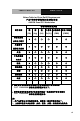
Touch Panel PC AHP-2176 Below Table for China RoHS Requirements 产品中有毒有害物质或元素名称及含量 AAEON Panel PC/ Workstation 有毒有害物质或元素 部件名称 铅 汞 镉 (Pb) (Hg) (Cd) (Cr(VI)) (PBB) (PBDE) × ○ ○ ○ ○ ○ × ○ ○ ○ ○ ○ × ○ ○ ○ ○ ○ × ○ ○ ○ ○ ○ 硬盘 × ○ ○ ○ ○ ○ 液晶模块 × ○ ○ ○ ○ ○ 光驱 × ○ ○ ○ ○ ○ 触控模块 × ○ ○ ○ ○ ○ 电源 × ○ ○ ○ ○ ○ 印刷电路板 六价铬 多溴联苯 多溴二苯醚 及其电子组件 外部信号 连接器及线材 外壳 中央处理器 与内存 O:表示该有毒有害物质在该部件所有均质材料中的含量均在 SJ/T 11363-2006 标准规定的限量要求以下。 X:表示该有毒有害物质至少在该部件的某一均质材料中的含量超出 SJ
Touch Panel PC AHP-2176 Contents Chapter 1 General Information 1.1 Introduction ................................................................ 1-2 1.2 Specification .............................................................. 1-3 1.3 Dimension ................................................................. 1-6 Chapter 2 Hardware Installation 2.1 Panelmount Installation ............................................. 2-2 2.2 Hard Disk Drive Installation .......................................
Touch Panel PC AHP-2176 Chapter 1 General Information Chapter 1 General Information 1- 1
Touch Panel PC AHP-2176 1.1 Introduction ® ® The AHP-2176 operator panel is an onboard Intel Celeron 827E 1.4GHz processor computer that is designed to serve as a human machine interface (HMI). It is a PC-based system with 17" color TFT LCD display, onboard Ethernet controller, multi-COM port interfaces and an audio controller. With a built-in CFast™ socket, the AHP-2176 is as compact and user friendly as a multi-function computer.
Touch Panel PC AHP-2176 1.2 Specification System CPU ® ® Onboard Intel Celeron 827E 1.4GHz Processor System Memory DDR3 800/1066/1333 MHz (204 pin) x 2, SODIMM, Max. 8GB Ethernet 10/100/1000Base-T, RJ-45 x 2 LCD / CRT Controller Integrated in Processor I/O Port USB2.0 x 4 (2 on front, 2 on rear) DB-9 RS-232 x 4 (COM3/4/5/6) LAN x 2 VGA x 1 Line-out x 1 Power switch x 1 Storage Disk Drive CFast™ slot x 1 (Internal); 2.
Touch Panel PC Dimension AHP-2176 16.5”(W) x 14.1”(H) x 2.8”(D) (420mm x 358mm x 97mm) Carton Dimension 26”(W) x 8.11”(H) x 19.53”(D) (661mm x 206mm x 496mm) Net Weight 17.9 lb (8.1 kg) Gross Weight 23.1 lb (10.
Touch Panel PC AHP-2176 LCD Display Type 17” TFT LCD Max. Resolution 1280x1024 Max. Colors 16.
Touch Panel PC AHP-2176 1.3 Dimension AHP- 2 1 7 6 UNITS: m m 4 1 9 .7 6 9 7.30 3 5 7 .7 9 3 3 8 .0 3 1 0 0 .0 0 3 4.75 1 0 0 .0 0 3 0 0 .0 0 4 0 4 .
Touch Panel PC AHP-2176 Chapter 2 Hardware Installation Chapter 2 Quick Installation Guide 2-1
Touch Panel PC AHP-2176 2.1 Panelmount Installation The display panel can be mounted into the wall. You will need the screws along with the mounting brackets, which be packed in the accessory box. Follow the steps below: Before you start to follow the instructions, please place the display panel into the wall. See the following illustration on the left. Step 1: Place the mounting brackets and plug the screw. Step 2: Aim the mounting set at the hole on the monitor.
Touch Panel PC 1 2 AHP-2176 3 4 Complete Illustration Chapter 2 Quick Installation Guide 2 - 3
Touch Panel PC AHP-2176 2.
Touch Panel PC AHP-2176 2.
Touch Panel PC Step 3: Fasten the Hard Disk onto the bracket Chapter 2 Quick Installation Guide 2 - 6 AHP-2176
Touch Panel PC AHP-2176 Step 4: Fasten the screws of the hard disk bracket onto the AHP-2176 Chapter 2 Quick Installation Guide 2 - 7
Touch Panel PC AHP-2176 Chapter 3 AMI BIOS Setup Chapter 3 AMI BIOS Setup 3-1
Touch Panel PC AHP-2176 3.1 System Test and Initialization These routines test and initialize board hardware. If the routines encounter an error during the tests, you will either hear a few short beeps or see an error message on the screen. There are two kinds of errors: fatal and non-fatal. The system can usually continue the boot up sequence with non-fatal errors. System configuration verification These routines check the current system configuration stored in the CMOS memory and BIOS NVRAM.
Touch Panel PC AHP-2176 3.2 AMI BIOS Setup AMI BIOS ROM has a built-in Setup program that allows users to modify the basic system configuration. This type of information is stored in battery-backed CMOS RAM and BIOS NVRAM so that it retains the Setup information when the power is turned off. Entering Setup Power on the computer and press or immediately. This will allow you to enter Setup. Main Set the date, use tab to switch between date elements.
Touch Panel PC Setup Menu Setup submenu: Main Chapter 3 AMI BIOS Setup 3-4 AHP-2176
Touch Panel PC AHP-2176 Setup submenu: Advanced Chapter 3 AMI BIOS Setup 3-5
Touch Panel PC AHP-2176 ACPI Settings Options Summary : ACPI Sleep State Suspend Disabled S1 (CPU Stop Clock) S3 (Suspend to RAM) Default Select the Highest ACPI sleep state the system will enter when the SUSPEND button is pressed.
Touch Panel PC AHP-2176 Trusted Computing Option Summary : TPM SUPPORT Disable Default Enable Enables or Disables TPM support. O.S. will not show TPM. Reset of platform is required.
Touch Panel PC AHP-2176 CPU Configuration Options Summary : Intel Disabled Virtualization Enabled Default Technology When enabled, a VMM can utilize the additional hardware capabilities provided by Vanderpool Technology Chapter 3 AMI BIOS Setup 3-8
Touch Panel PC AHP-2176 SATA Configuration (IDE) Options Summary : SATA Enabled Default Controller(s) Disabled Enable or disable SATA Device. SATA Mode IDE Default Selection AHCI RAID Determines how SATA controller(s) operate.
Touch Panel PC AHP-2176 IDE Configuration (AHCI) Options Summary : SATA Controller(s) Disabled Enabled Default Enable or Disable SATA Port. SATA Mode Selection IDE AHCI Selected RAID Determines how SATA controller(s) operate. SATA Port 0 Hot Plug Disable Default Enabled Designates this port as Hot Pluggable. SATA Port 1 Hot Plug Disable Default Enabled Designates this port as Hot Pluggable. SATA Port 2 Hot Plug Disable Default Enabled Designates this port as Hot Pluggable.
Touch Panel PC SATA Port 3 Hot Plug Disable Enabled Designates this port as Hot Pluggable. SATA Port 4 Hot Plug Disable Enabled Designates this port as Hot Pluggable.
Touch Panel PC AHP-2176 IDE Configuration (RAID) Options Summary : SATA Controller(s) Disabled Enabled Default Enable or Disable SATA Port. SATA Mode IDE AHCI RAID Selected Determines how SATA controller(s) operate. SATA Port 0 Hot Plug Disable Default Enabled Designates this port as Hot Pluggable. SATA Port 1 Hot Plug Disable Default Enabled Designates this port as Hot Pluggable. SATA Port 2 Hot Plug Disable Default Enabled Designates this port as Hot Pluggable.
Touch Panel PC SATA Port 3 Hot Plug Disable Enabled Designates this port as Hot Pluggable. SATA Port 4 Hot Plug Disable Enabled Designates this port as Hot Pluggable.
Touch Panel PC AHP-2176 PCH-FW Configuration Options Summary : Firmware Update Configuration Configure Management Engine Technology Parameters.
Touch Panel PC AHP-2176 Firmware Update Configuration Options Summary : Me FW Image Disabled Default Re-Flash Enabled Enable/Disable Me FW Image Re-Flash function.
Touch Panel PC AHP-2176 USB Configuration Options Summary : Legacy USB Support Enabled Default Disabled Auto Enable Legacy USB support. AUTO option disables legacy support if no USB devices are connected. DISABLE option will keep USB devices available only for EFI applications.
Touch Panel PC AHP-2176 Super IO Configuration Options Summary : Serial Port 3 Configuration Serial Port 4 Configuration Serial Port 5 Configuration Serial Port 6 Configuration Power Saving Function Set Parameters of Serial Port 3 (COMC) Set Parameters of Serial Port 4 (COMD) Set Parameters of Serial Port 5 (COME) Set Parameters of Serial Port 6 (COMF) Disabled Default Enabled Enable to reduce power consumption is system off state. When Enabled, only power button can power-up system.
Touch Panel PC AHP-2176 Serial Port 3 Configuration Options Summary : Serial Port Enabled Default Disabled Enable or Disable Serial Port (COM) Change Settings Auto Default IO=3E8h; IRQ=5; IO=2E8h; IRQ=5; IO=2D0h; IRQ=5’ IO=2D8h; IRQ=5; Select an optimal setting for Super IO device.
Touch Panel PC AHP-2176 Serial Port 4 Configuration Options Summary : Serial Port Enabled Default Disabled Enable or Disable Serial Port (COM) Change Settings Auto Default IO=2E8h; IRQ=5; IO=3E8h; IRQ=5; IO=2D0h; IRQ=5; IO=2D8h; IRQ=5; Select an optimal setting for Super IO device.
Touch Panel PC AHP-2176 Serial Port 5 Configuration Options Summary : Serial Port Enabled Default Disabled Enable or Disable Serial Port (COM) Change Settings Auto Default IO=2D0h; IRQ=5; IO=3E8h; IRQ=5; IO=2E8h; IRQ=5; IO=2D8h; IRQ=5; Select an optimal setting for Super IO device.
Touch Panel PC AHP-2176 Serial Port 6 Configuration Options Summary : Serial Port Enabled Default Disabled Enable or Disable Serial Port (COM) Change Settings Auto Default IO=2D8h; IRQ=5 IO=3E8h; IRQ=5; IO=2E8h; IRQ=5; IO=2D0h; IRQ=5; Select an optimal setting for Super IO device.
Touch Panel PC H/W Monitor Chapter 3 AMI BIOS Setup 3-22 AHP-2176
Touch Panel PC AHP-2176 Setup submenu: Chipset Chapter 3 AMI BIOS Setup 3-23
Touch Panel PC System Agent (SA) Configuration Options Summary : Graphics Configuration Config Graphics Settings.
Touch Panel PC AHP-2176 Graphics Configuration Options Summary : Internal Graphics Auto Default Disabled Enabled Keep IGD enabled based on the setup options.
Touch Panel PC AHP-2176 384M 416M 448M 480M 512M Select DVMT 5.0 Pre-Allocated (Fixed) Graphics Memory size used by the Internal Graphics Device. DVMT Total Gfx Men 128M 256M MAX Default Select DVMT5.0 Total Graphic Memory size used by the Internal Graphics Device.
Touch Panel PC AHP-2176 Display Control Options Summary : Boot Display Select VBIOS Default Default CRT LVDS CRT+LVDS Select the Video Device during POST and DOS. This has no effect if external graphics present.
Touch Panel PC AHP-2176 1680x1050 1280x800 1920x1080 Select LCD panel used by Internal Graphics Device by selecting the appropriate setup items.
Touch Panel PC AHP-2176 PCH-IO Configuration Options Summary : Power Mode ATX Type Default AT Type Select power supply mode. Restore AC Power Power off Loss Power on Last State Default Select AC power state when power is re-applied after a power failure. Azalia Disabled Enabled Auto Default Control Detection of the Azalia device. Disabled = Azalia will be unconditionally disabled Enabled = Azalia will be unconditionally Enabled Auto = Azalia will be enabled if present, disabled otherwise.
Touch Panel PC AHP-2176 Enable or disable internal HDMI codec for Azalia. Azalia HDMI codec Disabled Default Port B Enabled Enable or disable internal HDMI codec Port for Azalia. Azalia HDMI codec Disabled Port C Enabled Default Enable or disable internal HDMI codec Port for Azalia. Azalia HDMI codec Disabled Default Port D Enabled Enable or disable internal HDMI codec Port for Azalia. PCH LAN Controller Enabled Default Disabled Enable or disable onboard NIC.
Touch Panel PC AHP-2176 Setup submenu: Boot Options Summary : Quiet Boot Disabled Enabled Default Enables or disables Quiet Boot option Launch I82579LM PXE Disabled Default OpROM Enabled Enable or Disable Legacy Boot Option for I82579LM.
Touch Panel PC Hard Drives BBS Priorities Chapter 3 AMI BIOS Setup 3-32 AHP-2176
Touch Panel PC AHP-2176 Submenu: Security Change User/Supervisor Password You can install a Supervisor password, and if you install a supervisor password, you can then install a user password. A user password does not provide access to many of the features in the Setup utility. If you highlight these items and press Enter, a dialog box appears which lets you enter a password. You can enter no more than six letters or numbers. Press Enter after you have typed in the password.
Touch Panel PC Setup submenu: Exit Chapter 3 AMI BIOS Setup 3-34 AHP-2176
Touch Panel PC AHP-2176 Chapter 4 Driver Installation .
Touch Panel PC AHP-2176 The AHP-2176 comes with an AutoRun DVD-ROM that contains all drivers and utilities that can help you to install the driver automatically. Insert the driver DVD, the driver DVD-title will auto start and show the installation guide. If not, please follow the sequence below to install the drivers.
Touch Panel PC 4.1 AHP-2176 Installation: Insert the AHP-2176 DVD-ROM into the DVD-ROM drive. And install the drivers from Step 1 to Step 8 in order. Step 1 – Install Chipset Driver 1. Click on the STEP 1-CHIPSET folder and double click on the infinst_autol.exe file 2. Follow the instructions that the window shows 3. The system will help you install the driver automatically Step 2 – Install VGA Driver 1. Click on the STEP2-VGA folder and select the OS folder your system is 2. Double click on the .
Touch Panel PC AHP-2176 dotNet Framwork folder. Step 3 –Install Audio Driver 1. Click on the STEP3-AUDIO folder and select the OS folder your system is 2. Double click on the .exe located in each OS folder 3. Follow the instructions that the window shows 4. The system will help you install the driver automatically Step 4 –Install LAN Driver 1. Click on the STEP4-LAN folder and select the folder of intel_82579 or realtek_8111E based on the LAN chipset in your system. 2.
Touch Panel PC AHP-2176 Step 6 – Install TPM Driver 1. Click on the STEP6-TPM folder and double click on the Setup.exe file 2. Follow the instructions that the window shows 3. The system will help you install the driver automatically Step 7 – Install Touch Panel Driver 1. Click on the STEP7-Touch Panel Driver folder and select the OS folder your system is 2. Double click on the setup.exe file located in each OS folder 3. Follow the instructions that the window shows 4.
Touch Panel PC AHP-2176 1. Create a password for Administrator account. 2.
Touch Panel PC AHP-2176 3. Reboot and Administrator login. 4. To run patch.bat with [Run as administrator].
Touch Panel PC Chapter 4 Driver Installation 4 -8 AHP-2176
Touch Panel PC AHP-2176 Appendix A Programming the Watchdog Timer Appendix A Programming the Watchdog Timer A-1
Touch Panel PC AHP-2176 A.
Touch Panel PC AHP-2176 ********************************************************************************* *** // SuperIO relative definition (Please reference to Table 1) #define byte SIOIndex //This parameter is represented from Note1 #define byte SIOData //This parameter is represented from Note2 #define void IOWriteByte(byte IOPort, byte Value); #define byte IOReadByte(byte IOPort); // Watch Dog relative definition (Please reference to Table 2) #define byte TimerLDN //This parameter is represented from
Touch Panel PC AHP-2176 #define byte WDTRstBit // This parameter is represented from Note22 #define byte WDTRstVal // This parameter is represented from Note23 ********************************************************************************* *** ********************************************************************************* *** VOID Main(){ // Procedure : AaeonWDTConfig // (byte)Timer : Time of WDT timer.(0x00~0xFF) // (boolean)Unit : Select time unit(0: second, 1: minute).
Touch Panel PC AHP-2176 VOID WDTEnableDisable(byte LDN, byte Register, byte BitNum, byte Value){ SIOBitSet(LDN, Register, BitNum, Value); } VOID WDTParameterSetting(){ // Watchdog Timer counter setting SIOByteSet(TimerLDN, TimerReg, TimerVal); // WDT counting unit setting SIOBitSet(UnitLDN, UnitReg, UnitBit, UnitVal); // WDT output mode setting, level / pulse SIOBitSet(ModeLDN, ModeReg, ModeBit, ModeVal); // Watchdog timeout output via WDTRST# SIOBitSet(WDTRstLDN, WDTRstReg, WDTRstBit, WDTRstVal); } VOID
Touch Panel PC AHP-2176 VOID SIOBitSet(byte LDN, byte Register, byte BitNum, byte Value){ Byte TmpValue; SIOEnterMBPnPMode(); SIOSelectLDN(byte LDN); IOWriteByte(SIOIndex, Register); TmpValue = IOReadByte(SIOData); TmpValue &= ~(1 << BitNum); TmpValue |= (Value << BitNum); IOWriteByte(SIOData, TmpValue); SIOExitMBPnPMode(); } VOID SIOByteSet(byte LDN, byte Register, byte Value){ SIOEnterMBPnPMode(); SIOSelectLDN(LDN); IOWriteByte(SIOIndex, Register); IOWriteByte(SIOData, Value); SIOExitMBPnPMode(); } ****
Touch Panel PC AHP-2176 Appendix B I/O Information Appendix B I/O Information B - 1
Touch Panel PC B.
Touch Panel PC AHP-2176 Appendix B I/O Information B - 3
Touch Panel PC B.
Touch Panel PC AHP-2176 B.
Touch Panel PC Appendix B I/O Information B - 6 AHP-2176
Touch Panel PC AHP-2176 B.