
Instruction Manual


4
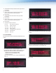
Reading Unit Connector
Detecting Unit Connector
4-20 mA
Connector
5.0 Connecting to 4-20 mA Output
The unit connects to the host control/monitoring system via a standard
“3-wire” analog loop.
There are three terminals for this connection labeled as follows:
• +24V Positive 24 VDC
• GND 24 VDC common
• 4-20mA Signal to the analog input of the host system.
The 24 VDC power for the unit must be connected to the same source
as the host control/monitoring system, and in particular the 24 VDC
common (GND) must be the same as is used for reference by the
analog input module in the host control/monitoring system. (Figure 4)
1. The Communications Module will not enter the menu system if
data is being transmitted. Transmitting notice will be shown on
the LCD display.
2. Press any of the three buttons to enter the menu system. If the
unit is not transmitting data, you will enter the menu system
immediately. If the unit is transmitting data, you will enter the
menu system once the transmitting procedure is complete.
3. When the Communications Module is in the menu, the selected
eld will blink.
4. Use the UP and DOWN buttons to increase /decrease the setting
of that eld.
5. Use the OK button to select the value and scroll to the next eld.
6. If Exit (EXT) eld is reached using the OK button, press either
UP or DOWN to exit from menu system back into main mode.
7. After setting the time and date, it is recommended to initialize the
sensors. Once you leave the time/ date setup menu, the device
will ask if the sensors should be initialized. Press the UP button to
initialize the sensors or press DOWN to exit the menu system.
Note: The Communications Module will conduct the next data
transmission when the scheduled time comes though the LCD
display will NOT change to show this transmission. The red LED
on the left of the LCD display will blink at a faster rate when the
transmission is taking place.
7.0 Programming Instructions
When programming your building management software to receive
the 4-20 mA signal from the SAAFShield CM, you can utilize three
different languages: structured text, ladder logic, and function block
diagram. Please refer to AAF document SAAFShield Appendix
GPF-3-118, “Detailed Programming Instructions for SAAFShield
Communications Module.”
Up Button Down Button OK Button
6.0 Menu System
The SAAFShield Communications Module has three push buttons
to the right of the LCD display (Figure 5). Press any button to enter
the menu.
Figure 5.
Figure 4.