
Owner`s manual

9
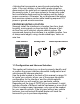
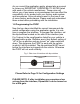
Once you’ve identified the constant 12V+ circuit, strip
back about 1/8” of the insulation. Now take the positive
test lead and insert it into the wire stranding so that you
can now probe for a suitable ground location in the dash
cavity using the negative test lead. Bare chassis metal is
the recommended ground spot. The voltmeter will read a
constant 12 volts or higher when you have found a good
ground point. Attach the BLACK ground wire to this spot
with either an existing bolt or screw or use a metal piercing
screw. You also have the option of splicing into the ground
wire in the main radio harness. Probe the remaining wires
with the negative test lead until you again find a circuit that
reads a constant 12 volts on the voltmeter. When you’ve
found a circuit that reads constant 12 volts, turn the dash
light dimmer control to make sure you have not probed the
illumination dimmer circuit. If the circuit continues to read
a constant 12 volts or higher regardless of the dimmer
position, you have found the ground wire. If not, continue
testing until you do. Some vehicles do not have a ground
wire in their main radio harness and instead ground through
their mounting brackets to the dash. In these cases, you
will have to ground the black wire to the bare metal chassis
inside the dash . Once the ground wire is connected, please
finish your wiring connections by splicing in the external
YELLOW wire from the vehicle specific harness.
Vehicle Specific Harnesses that require wiring
connections:
PXHFD1 – connect the Yellow wire to constant 12V+ &
connect the Black wire to ground.
PXHFD2 – connect the Yellow wire to constant 12V+ &
connect the Black wire to ground.
PXHFD3 – connect the Yellow wire to constant 12V+ &
connect the Black wire to ground.
PXHGM3 – connect the Yellow wire to constant 12V+ &
connect the Black wire to ground.
PXHVW2 – connect both the Black and Black/White wires to
ground.