
Manual


14
Electrical
Check the unit data plate to make sure it matches the
power supply. Connect power to the unit according to
the wiring diagram provided with the unit. The power
and control wiring may be brought in through the utility
entry. Do not run power and control wires in the same
conduit.
Protect the branch circuit in accordance with code
requirements. The units must be electrically grounded
in accordance with the National Electric Code, ANSI /
NFPA No. 70. In Canada use current C.S.A. Standard
C22.1, Canadian Electric Code Part 1.
Connect power wiring to the terminal block, or optional
disconnect switch. The manufacturer has done all
wiring beyond this point, and cannot be modified
without affecting the unit’s agency and/or safety
certification, and warranty.
Power can be applied to the unit after the control
wiring is connected.
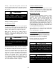
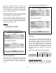
Standard Control Board
This printed circuit board is the central control point for
all the electrical components in the unit. Low voltage
terminals are provided for connection to the wall
mounted thermostat of the customer’s selection, or as
furnished by AAON.
Confirm the optional features that were specified and
purchased with the HB conditioner. This will allow
proper selection of the number of control options listed
below that may need additional wiring.
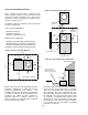
Install gas fired units so that the flue discharge
vent is located a minimum of 120” from openings
through which combustion products can enter the
building. Never point flue discharge in direction of
air intake for other equipment. Unit location must
assure combustion and ventilation airflows are
never obstructed.
WARNING
If the supply or warm air duct passes through a
combustible roof, a clearance of one inch must be
maintained between the outside edges of the duct
and combustible material in accordance with
National Fire Protection Association Standard No.
90A. Provide flashings or enclosure between
structure, and roof. All joints must be sealed with
mastic to ensure a watertight seal.
All roofing work should be performed by qualified
roofing contractors.
CAUTION
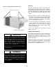
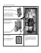
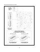
Outside Air Hood (Optional)
Lifting lug on each corner
Figure 14a, Lifting Lugs and Outside Air Hood