Operating & Installation Manual The Becton MK 2 Range of Gas Stoves (Becton 7 With Add On Canopy) PLEASE RETAIN THESE INSTRUCTIONS FOR FUTURE REFERENCE FOR USE IN COUNTRIES GB & IE Rev 9
Congratulations on your choice of an Aarrow Stove. More than 20 years experience has been put into the development of our Becton Family to ensure ultimate performance and years of trouble free enjoyment. Every detail on the fire has been carefully engineered and designed which is why we are so confident in the reliability of our product that we offer a Lifetime Guarantee.
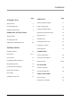
CONTENTS Page INTRODUCTION Page SERVICING Safety Notices 4 Details of Pilot Assembly 17 General Information 4 Glass & Trim Fitting 18 Statutory Requirements 5 Component Replacement 19 Replacement of the Door Seal 19 Regular Service 19 Annual Service 20 Cleaning Outer Services 19 Cleaning Door Glass 20 Fault Diagnosis 21 OPERATING INSTRUCTIONS Technical Data 6 Arranging the Coals 6 Lighting & Controlling The Fire 8/9 INSTALLATION Installing The Fire Flue System 10 10/11 SPA
INTRODUCTION References in this manual to British Standards and Statutory Regulations and Requirements apply only to the United Kingdom. For Ireland the rules in force must be used. Before installation, check that the local distribution conditions, nature of the gas, pressure and the adjustment of the appliance are compatible. The manual is an important part of the appliance and must by law be handed to the end user on completion of the installation. normal hygiene rules are followed.
INTRODUCTION IMPORTANT NOTICES A qualified gas engineer must carry out the installation and servicing of this appliance in accordance with these instructions and in compliance with current Building Regulations. Such person must be a registered CORGI engineer. This appliance is designed to run on natural gas only. Warning - Only use the appliance with the specified gas. The fire is fitted with a safety device to shut down the appliance if there is inadequate flue draw.
OPERATING INSTRUCTIONS FIRE DIMENSIONS TECHNICAL DATA Category I2H For use in GB and IE at a supply pressure of 20mbar Becton Bunny Natural Gas Becton 7 Natural Gas Main Burner Aeromatic AC13/112511 (mod 263) Aeromatic AC13/112511 (mod 263) Injector Bray 82-700 Bray 82-700 Max. Heat Setting Heat Input (net) 3.3 kW 4.2 kW Heat Output (net) 2.2 kW 2.8 kW 0.349 m3/hour 0.444 m3/hour Gas Rate Cold Setting Pressure 3.5mb 2.0 kW 2.6 kW Heat Output (net) 1.4 kW 1.8 kW Gas Rate 0.
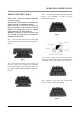
OPERATING INSTRUCTIONS ARRANGING THE COALS Safety Notice - Please see SAFETY NOTICES ref. Coal set page 4. Warning: The coals and the coal matrices are fragile ensure they are handled carefully. Ensure location is correct. Do not force the matrix into position. If the coals and/or the coal matrices are damaged they must be replaced with genuine Aarrow replacement sets. Warning: An incorrect coal layout may cause soot to build up inside the fire and therefore invalidate the guarantee.
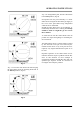
OPERATING INSTRUCTIONS LIGHTING THE FIRE & CONTROLLING Step 1c. Keep the control knob pressed in for a further 15 seconds and then release. The pilot will remain alight. Under no circumstance must the fire be operated with the fire-door open or if the glass is cracked or broken. If pilot does not remain alight repeat this procedure. Open the gas control access door situated at the bottom of the appliance. Step 1a.
OPERATING INSTRUCTIONS Step 4. To extinguish the pilot, turn the control knob to the OFF position. (Fig 4f) Incorporated into the pilot assembly is a flame failure device designed to shut off the gas supply in the event of the pilot flame being extinguished while the fire is unattended. Should the pilot flame blow out accidentally or intentionally whilst the fire is running, no attempt should be made to re-light the gas for at least three minutes.
INSTALLATION INSTALLING THE FIRE Your CORGI qualified gas engineer should install the fire in accordance with the following regulations and standards:The Gas Safety (Installation and Use) Regulations 1998 (as amended). The Building Regulations for England and Wales 2000 ref; Approved Document J 2002 edition (issued by the DTLR). The Building Standards (Scotland) (Consolidation) Regulations. BS5440 parts 1 and 2 1990, BS5871 And these Installation Instructions.
INSTALLATION It is recommended that a smoke test is performed inside the fire to ensure that adequate flue draw is evident. REAR FLUE Open Hearth Fit and seal a ‘T’ section (with soot box) directly into the flue spigot. The maximum horizontal section allowed is 150mm. Provide a minimum vertical height of 600mm of flue from the height of the rear flue outlet. See figure 6b. Fig 6a. non- combustible closure plate, incorporating access for cleaning debris.
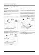
INSTALLATION FIRE LOCATION The appliance must not be installed in a room or space, which contains a bath or shower. This fire is designed for use with either top or rear flue outlets and must be mounted on a hearth with a minimum of 12mm non-combustible material thickness. There must be a minimum of 200mm clearance from the sides of the fire to any combustible sidewalls. Fig6b. For clearance from the top of the fire to any combustible shelf. Fig 6a. (See Graph 1).
INSTALLATION The minimum height from the extreme top surface of the fire to the underside of a shelf or other projection made of wood or any other combustible material is shown on graph 1. Graph 1.Combustible Shelf Clearances The recommended minimum height from the extreme top surface of the fire to the underside of a non combustible shelf is 100mm.
INSTALLATION HEARTH REQUIREMENTS To comply with current Building Regulations the fire must stand on a fireproof hearth, which has an upper fireproof layer of 12mm non-combustible material. If the rear of the fire is to be pushed up against a surface it must be of a non-combustible material. The hearth must protrude at least 25mm in front of the glass window and 150mm either side. The hearth must not be capable of inadvertent covering by a carpet or rug.
INSTALLATION FIRE TESTING Flame failure device testing Step 1 Ignite the appliance in accordance with page 9 and run for 60 seconds. Warning: The spillage monitoring system is a safety feature required by law and must not be adjusted or put out of action by the installer. If the spillage monitoring system or any of its parts are to be replaced, only original manufacturers parts are to be used. Step 2 Turn the appliance off to extinguish the pilot, listen for a snap at the control valve.
INSTALLATION CHECK LIST CHECKLIST Hearths, Fireplaces, Flues and chimneys This checklist is to ensure hearths, fireplaces, flues and chimneys are satisfactory, and to show what you have done to comply with the requirements of The Building Regulations 2000 Approved Document J 2002. 1. Building address, where work has been carried out....................................................................................................................................... .........................................
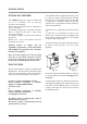
SERVICING DETAIL OF PILOT ASSEMBLY It is strongly recommended to leave the pilot on permanently. This will keep the fire and its components, including the ceramic coal set in a warmer state and give instant ignition to the burner. This in turn will reduce condensation in the chimney and any flue problems associated with this. Fig.
SERVICING DOOR TRIM Becton fire doors are fitted with a brushed steel finish trim as standard. This, clips on to the small lugs at the top and bottom of the aperture in the cast iron fire door, as a "spring fit". When fitted, the trim locks the glass retaining clips in position. (Fig 10) The fire door should be removed so that the above operations can be carried out on a workbench or similar. Remove the door by GENTLY tapping the door upwards; this will lift off of its hinges. Trim Fit. Fig.
SERVICING COMPONENT REPLACEMENT Step 1 Ensure the fire is cold. Turn off the gas supply at the gas service cock. Step 2 Remove the coals. Step 3 Remove the rear matrix plate, undo the three retaining nuts. Step 4 Remove the control valve heat shield. Undo the two retaining screws located on the left-hand side of the shield. Slide the heat shield backwards and lift out carefully. Do not damage the covering. Step 5 Disconnect the gas supply pipe at inlet to fire. Step 4a Becton 7.
SERVICING ANNUAL SERVICE THIS GAS APPLIANCE MUST BE SERVICED EVERY TWELVE MONTHS BY A QUALIFIED GAS ENGINEER. See "SAFETY NOTICES" ref coal set page 4. Step 1 Isolate the gas supply to the fire using the gas cock supplied at installation. Step 2 With the appliance cold, open the main door by turning the handle through 180° degrees. CLEANING OUTER SURFACES To clean the outside first the appliance must be cold.
SERVICING FAULT DIAGNOSIS START Does the pilot ignite? Does the pilot stay alight? Yes Does the main burner light? Yes Yes Fire satisfactory No No Is the gas supply turned on? Is their air in the system? No Is the supply pressure correct? No No Correct pressure Is the thermocouple o.k.
SERVICING GENERAL COMPONENTS Spare parts can be obtained by contacting the original supplier of the fire or Aarrow Fires. Fire Body Ancillary Components. Only use genuine Aarrow parts. ACCESSORIES AND OPTIONS Elegant stands Are available for the complete Becton Fire range. The addition of a stand increases the height of the flue by approximately 105mm.
NOTES Becton Bunny & Becton 7 MK2 Gas stoves 23
NOTES 24 Becton Bunny & Becton 7 MK2 Gas stoves
SPARE PARTS Part Description Visual Aid (not to scale) Bunny Mk 2 Part No. Becton 7 Mk2 Part No. 1. Becton 7 Mk 2 Coal Set AFGS088 1a. Becton Bunny Mk 2 Coal Set AFGS088A 2. Co-pilot Assembly AFGS089 AFGS089 AFGS090 AFS090 AFS091A AFS091 AFS1042 AFS1042 AFS047 AFS047 3. Elbow Injector 4. Gas Control Valve 5. Control Door Magnet. 6. Hinge Kit To Fit Both Doors Comprises 2 Hinges & 4 Fixings Per Set.
SPARE PARTS Part Description Visual Aid (not to scale) Bunny Mk 2 Part No. Becton 7 Mk 2 Part No. AFGS039 AFGS039 AFGS098 AFGS098 AFGS092A AFGS092 AFGS080 AFGS080 AFS094A AFS095 AFGS097 AFGS037A AFS069 AFS088 7. Fire Door Locking Assembly 8. Control Door Handle Assembly 9. Burner & Fixing 10. Pipe Set Complete With Connectors 11. Decorative Door Surround 12. Main Door Assembly Complete With Handle, Glass, Gaskets, Clips and Seal. 13.
SPARE PARTS Part Description Visual Aid (not to scale) Bunny Mk 2 Part No. Becton 7 Part No. AFS070 AFS089 AFGS064 AFS010 AFGS063 AFGS040 14. Gasket Kit Inc. Clips 15. Hotplate 16. Flue Outlet Spigot 17. Becton 7 Mk 2 Gas Fire Door Rope Kit With Door Rope Glue. 18. Becton Bunny Mk 2 Fire Door Rope Kit With Door Rope Glue. 19. Becton Bunny Mk 2 Reflective Panels AFS048 AFGS099 AFGS062 19a.
SPARE PARTS Part Description Visual Aid (not to scale) Bunny Mk 2 Part No. Becton 7 Part No. AFGS093 AFGS093 AFGS094 AFGS094 AFGS025 AFGS025 20. Large Ceramic Panel 21. Small Ceramic Panel 22.
GUARANTEE GUARANTEE Once again we would like to thank you for buying a Becton fire. All Guarantee periods commence on the date of purchase and are non-transferable. When you buy an Aarrow Fire, you are not only buying a first class appliance - you are buying a commitment from us to look after you and your appliance for as long as you want. Our Lifetime Guarantee is offered as an addition to your statutory rights.
SERVICE RECORD Date of Visit Company Work Carried Out Signature Should you have any questions about your Becton Multifuel Stove that is not covered in this manual please contact your Aarrow retailer. Please keep all repair receipts safely. Please ensure you have this manual available when an engineer visits as they will complete the service record chart.
Lifetime Guarantee For your peace of mind Aarrow Fires gives a Lifetime Guarantee against manufacturing defects of the main body* of its Becton range of fires. Additionally, all other parts are covered by a one year no quibble replacement guarantee. This guarantee covers replacement of the item only and does not extend to any other costs, including labour, incurred in its replacement. Documentation must be retained and produced in the event of a warranty claim.
FINAL FACTORY CHECK LIST Model.................................. Serial No............................. QUALITY FINISH COAL SET I’ve checked it and it’s O.K. REGISTRATION CARD REFLECTIVE PANELS DOOR HANDLE FLUE OUTLET Assembled by............................. Checked by ................................ HOTPLATE OPERATING INSTRUCTIONS GAS COCK Please ensure the enclosed registration card is completed and returned to Aarrow Fires and the following information completed for your own information.