
Datasheet


14
Dimensions (mm)
!"#$%&'
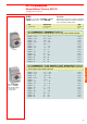
Connection terminal block for busbar
2 MS 325 1 !"#
Busbar connector for cross-wiring (2 x MS 325 with 1 auxiliary contact)
!4 MS 325 1 !"#
Busbar connector for cross-wiring (4 x MS 325 with 1 aux. contact)
25 mm
2
!"#$%
Connection terminal block for 25 mm
2
wires
MS 325 !"#$"%
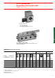
Power-Manual Motor Starters MS 325
!"#$% Circuit Diagrams and Accessories Dimensions
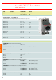
Legend
1 !
Undervoltage trip block
2 ! 1 NO + 1 NC 2 NO 2 NC
MS 325
Auxiliary contact block 1 NO + 2 NC, also as 2 NO or 2
NC in the case of MS 325
3 ! !"#1 1
“Tripped” alarm switch block (signal contact) 1 NO or 1 NC
SST 211 95 S
!"#$%&'% MS 325
Manual motor starter MS 325 with accessories as shown in the above
legend
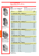
*90-232*
1SCA022426 R6210
1SCA022426 R6300
1SCA022384 R6940
1SCA022384 R7080
!
Door mounting set
!"#
Switch cabinet mounting set
!"#$
Drilling plan for Door mounting set
!"#$%
Drilling Plan for switch
cabinet mounting set
Dimensions
Circuit Diagrams
OH_1A_
OH_2A_