
Hardware Manual
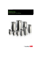


Table Of Contents
- List of related manuals
- Table of contents
- Safety instructions
- Introduction to the manual
- Operation principle and hardware description
- Mechanical installation
- What this chapter contains
- Safety
- Examining the installation site
- Necessary tools
- Moving the drive
- Unpacking and examining the delivery (frames R1 to R5)
- Unpacking and examining the delivery (frames R6 to R9)
- Installing the drive
- Flange mounting
- Cabinet installation
- Cooling
- Grounding inside the cabinet
- Installing drives above one another
- Planning the electrical installation
- What this chapter contains
- Limitation of liability
- Selecting the supply disconnecting device
- Selecting and dimensioning the main contactor
- Checking the compatibility of the motor and drive
- Protecting the motor insulation and bearings
- Requirements table
- Additional requirements for ABB motors of types other than M2_, M3_, M4_, HX_ and AM_
- Additional requirements for ABB high-output and IP23 motors
- Additional requirements for non-ABB high-output and IP23 motors
- Additional data for calculating the rise time and the peak line-to-line voltage
- Additional note for sine filters
- Selecting the power cables
- Selecting the control cables
- Routing the cables
- Implementing thermal overload and short-circuit protection
- Protecting the drive against ground faults
- Connecting drives to a common DC system
- Implementing the Emergency stop function
- Implementing the Safe torque off function
- Implementing the safety functions with the FSO module
- Implementing the ATEX-certified Safe motor disconnection function (option +Q971)
- Implementing the Power-loss ride-through function
- Using power factor compensation capacitors with the drive
- Using a contactor between the drive and the motor
- Implementing a bypass connection
- Protecting the contacts of relay outputs
- Connecting a motor temperature sensor to the drive I/O
- Electrical installation
- What this chapter contains
- Warnings
- Checking the insulation of the assembly
- Checking the compatibility with IT (ungrounded) systems
- Connecting the power cables
- DC connection
- Connecting the control cables
- Connecting a PC
- Controlling several drives through panel bus
- Installing optional modules
- Installation checklist
- Start-up
- Fault tracing
- Maintenance
- What this chapter contains
- Maintenance intervals
- Heatsink
- Fans
- Replacing the main cooling fan of frames R1 to R3
- Replacing the auxiliary cooling fan of IP55 frames R1 to R3
- Replacing the main cooling fan of frames R4 and R5
- Replacing the auxiliary cooling fan of frames R4 and R5 (IP55 and option +C135) and IP21 frame R5 types ACS880-01-xxxx-7
- Replacing the main cooling fan of frames R6 to R8
- Replacing the auxiliary cooling fan of frames R6 to R9
- Replacing the IP55 auxiliary cooling fan of frames R8 and R9
- Replacing the main cooling fans of frame R9
- Replacing the drive (IP21, UL Type 1, frames R1 to R9)
- Capacitors
- Memory unit
- Replacing the control panel battery
- Replacing safety functions modules (FSO-12, option +Q973)
- Technical data
- What this chapter contains
- Marine type-approved drives (option +C132)
- Ratings
- Derating
- Ambient temperature derating
- IP21 (UL Type 1) drive types and other IP55 (UL Type 12) types than listed in the following subheadings
- IP55 (UL Type 12) drive types -274A-2, 293A-3, -260A-5, -302A-5 and -174A-7
- IP55 (UL Type 12) drive type -240A-5
- IP55 (UL Type 12) drive types -363A-3 and -361A-5
- IP55 (UL Type 12) drive type -210A-7
- IP55 (UL Type 12) types -0430A-3, -0414A-5 and -0271A-7
- Altitude derating
- Deratings for special settings in the drive control program
- Ambient temperature derating
- Fuses (IEC)
- Fuses (UL)
- Dimensions. weights and free space requirements
- Losses, cooling data and noise
- Terminal and lead-through data for the power cables
- Terminal data for the control cables
- Electrical power network specification
- Motor connection data
- Control unit (ZCU-12) connection data
- Efficiency
- Protection classes
- Ambient conditions
- Materials
- Applicable standards
- CE marking
- Compliance with the EN 61800-3:2004
- UL marking
- “C-tick” marking
- EAC marking
- Approvals
- Cyber security disclaimer
- Disclaimer
- Dimension drawings
- What this chapter contains
- Frame R1 (IP21, UL Type 1)
- Frame R1 (IP55, UL Type 12)
- Frame R2 (IP21, UL Type 1)
- Frame R2 (IP55, UL Type 12)
- Frame R3 (IP21, UL Type 1)
- Frame R3 (IP55, UL Type 12)
- Frame R4 (IP21, UL Type 1)
- Frame R4 (IP55, UL Type 12)
- Frame R5 (IP21, UL Type 1)
- Frame R5 (IP55, UL Type 12)
- Frame R6 (IP21, UL Type 1)
- Frame R6 (IP55, UL Type 12)
- Frame R7 (IP21, UL Type 1)
- Frame R7 (IP55, UL Type 12)
- Frame R8 (IP21, UL Type 1)
- Frame R8 (IP55, UL Type 12)
- Frame R9 (IP21, UL Type 1)
- Frame R9 (IP55, UL Type 12)
- Safe Torque off function
- Resistor braking
- What this chapter contains
- Operation principle and hardware description
- Planning the braking system
- Mechanical installation
- Electrical installation
- Start-up
- Technical data
- Dimensions and weights of external resistors
- Common mode, du/dt and sine filters
- Further information

8
Jumpers and switches . . . . . . . . . . . . . . . . . . . . . . . . . . . . . . . . . . . . . . . . . . . . . . . 108
External power supply for the control unit (XPOW) . . . . . . . . . . . . . . . . . . . . . . . . . 109
AI1 and AI2 as Pt100, Pt1000, PTC and KTY84 sensor inputs (XAI, XAO) . . . . . . 109
Drive-to-drive link (XD2D) . . . . . . . . . . . . . . . . . . . . . . . . . . . . . . . . . . . . . . . . . . . . 110
DIIL input (XD24:1) . . . . . . . . . . . . . . . . . . . . . . . . . . . . . . . . . . . . . . . . . . . . . . . . . 110
DI6 (XDI:6) as PTC sensor input . . . . . . . . . . . . . . . . . . . . . . . . . . . . . . . . . . . . . . . 111
Safe torque off (XSTO) . . . . . . . . . . . . . . . . . . . . . . . . . . . . . . . . . . . . . . . . . . . . . . 111
Safety functions module connection (X12) . . . . . . . . . . . . . . . . . . . . . . . . . . . . . . . 111
Control cable connection procedure . . . . . . . . . . . . . . . . . . . . . . . . . . . . . . . . . . . . . . . 112
Connecting a PC . . . . . . . . . . . . . . . . . . . . . . . . . . . . . . . . . . . . . . . . . . . . . . . . . . . . . . . . . 114
Controlling several drives through panel bus . . . . . . . . . . . . . . . . . . . . . . . . . . . . . . . . . . . . 115
Installing optional modules . . . . . . . . . . . . . . . . . . . . . . . . . . . . . . . . . . . . . . . . . . . . . . . . . . 117
Mechanical installation of I/O extension, fieldbus adapter and pulse encoder interface
modules . . . . . . . . . . . . . . . . . . . . . . . . . . . . . . . . . . . . . . . . . . . . . . . . . . . . . . . . . . . . . 117
Wiring I/O extension, fieldbus adapter and pulse encoder interface modules . . . . . . . . 118
Installation of safety functions modules . . . . . . . . . . . . . . . . . . . . . . . . . . . . . . . . . . . . . 119
Installation procedure into Slot 2 . . . . . . . . . . . . . . . . . . . . . . . . . . . . . . . . . . . . . . . 119
Installation next to the control unit on frames R7 to R9 . . . . . . . . . . . . . . . . . . . . . . 121
7. Installation checklist
What this chapter contains . . . . . . . . . . . . . . . . . . . . . . . . . . . . . . . . . . . . . . . . . . . . . . . . . . 123
Checklist . . . . . . . . . . . . . . . . . . . . . . . . . . . . . . . . . . . . . . . . . . . . . . . . . . . . . . . . . . . . . . . . 123
8. Start-up
What this chapter contains . . . . . . . . . . . . . . . . . . . . . . . . . . . . . . . . . . . . . . . . . . . . . . . . . . 125
Startup procedure . . . . . . . . . . . . . . . . . . . . . . . . . . . . . . . . . . . . . . . . . . . . . . . . . . . . . . . . . 125
9. Fault tracing
What this chapter contains . . . . . . . . . . . . . . . . . . . . . . . . . . . . . . . . . . . . . . . . . . . . . . . . . . 127
LEDs . . . . . . . . . . . . . . . . . . . . . . . . . . . . . . . . . . . . . . . . . . . . . . . . . . . . . . . . . . . . . . . . . . . 127
Warning and fault messages . . . . . . . . . . . . . . . . . . . . . . . . . . . . . . . . . . . . . . . . . . . . . . . . 127
10. Maintenance
What this chapter contains . . . . . . . . . . . . . . . . . . . . . . . . . . . . . . . . . . . . . . . . . . . . . . . . . . 129
Maintenance intervals . . . . . . . . . . . . . . . . . . . . . . . . . . . . . . . . . . . . . . . . . . . . . . . . . . . . . 129
Descriptions of symbols . . . . . . . . . . . . . . . . . . . . . . . . . . . . . . . . . . . . . . . . . . . . . . . . . 130
Recommended annual maintenance actions by the user . . . . . . . . . . . . . . . . . . . . . . . 130
Recommended maintenance intervals after start-up . . . . . . . . . . . . . . . . . . . . . . . . . . . 130
Heatsink . . . . . . . . . . . . . . . . . . . . . . . . . . . . . . . . . . . . . . . . . . . . . . . . . . . . . . . . . . . . . . . . 130
Fans . . . . . . . . . . . . . . . . . . . . . . . . . . . . . . . . . . . . . . . . . . . . . . . . . . . . . . . . . . . . . . . . . . . 131
Replacing the main cooling fan of frames R1 to R3 . . . . . . . . . . . . . . . . . . . . . . . . . . . . 132
Replacing the auxiliary cooling fan of IP55 frames R1 to R3 . . . . . . . . . . . . . . . . . . . . . 133
Replacing the main cooling fan of frames R4 and R5 . . . . . . . . . . . . . . . . . . . . . . . . . . 134
Replacing the auxiliary cooling fan of frames R4 and R5 (IP55 and option +C135) and
IP21 frame R5 types ACS880-01-xxxx-7 . . . . . . . . . . . . . . . . . . . . . . . . . . . . . . . . . . . . 135
Replacing the main cooling fan of frames R6 to R8 . . . . . . . . . . . . . . . . . . . . . . . . . . . . 136
Replacing the auxiliary cooling fan of frames R6 to R9 . . . . . . . . . . . . . . . . . . . . . . . . . 137
Replacing the IP55 auxiliary cooling fan of frames R8 and R9 . . . . . . . . . . . . . . . . . . . 138