
Ideal Cutter User's Manual


8
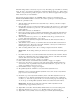
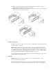
1. The guide grooves and all other moving parts of the clamp assembly.
2. The knife carrier guide channels (left and right). They are located between the knife guide
plates.
3. All moving parts of the knife drive system. To reach these parts, the lower machine cover
(#9) and / or the front table (#13) must be removed.
4. The back gauge spindle, its housing points, and the back gauge guide mechanism.
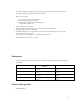
The lubrication chart indicates all points to which “EP” grease or oil must be applied
A full lubrication of the machine is recommended at least once in every third knife change.
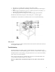
Wiring diagram
A wiring diagram for the machine is included in the electric switch box, which can be reached by
removing the front table (#13).
Troubleshooting
Should the machine cut out during operation, check the thermal overload switch (#10). If the
button of the thermal overload switch has popped out, it can be re-set after a short cooling period.
Should the thermal overload switch pop out again and cannot be re-set even after a few minutes,
please contact your service technician.
If the operator should detect any potentially dangerous defects, he should immediately call a
service technician and put the machine out of operation.
If defects or faults should occur which render repairs necessary, please contact your local
dealer.