
Installation User guide


58
UK
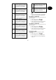
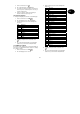
152 Additional outputs
Additional output 2
153 Additional outputs
Additional output 3
154 Additional outputs
Additional output 4
155 Additional outputs
Additional output 5
156 Additional outputs
Additional output 6
157 Additional outputs
Additional output 7
158 Additional outputs
Additional output 8
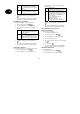
159 Inverting additional outputs
You can also invert the additional transistor outputs for
different applications. In inverted state, the voltage of
+12V is applied in active state – e.g.: for addressing a
visual signal.
1. On the control unit, enter:
159
2. The LCD display shows: 159: INV Pgby OFF
3. Via the keypad, select from the following items
and press:
00
inv Pgby OFF
+12V voltage is removed for activating
the output. In deactivated state, the
output is set to +12V.
01
Inv Pgby ON
+12V voltage is applied for activating
the output. In deactivated state, the
output is set to ground.
4. Confirm your input. On the control unit, enter:
.
5. The control unit acknowledges your input with a
double “beep” tone and shows Installer Mode.
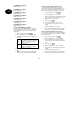
170 Prog. pulse outputs (time active)
The outputs programmed as active 1–4 are pulse-
addressed for a predefined time during activation of the
alarm centre as well as for fire and panic alarms. First
define the time in which these output are to be active.
1. On the control unit, enter: 170
2. The LCD display shows: 170: Set 1 01
3. Via the keypad, enter the time duration. Possible
values: are 00 for a latched output or a time
duration from 01 to 12 seconds.
4. To confirm, press:
5. The LCD display shows: 170: Set 2 01
6. In the same way, enter pulse time 2 via the
keypad.
7. Continue until all times are entered.
8. The control unit acknowledges your input with a
double “beep” tone and shows Installer mode.
171 Prog. pulse outputs (levels active)
Define when the outputs are to activated by defining the
type of activation/deactivation (A, B, C, D) for switching
the outputs to active.
1. On the control unit, enter: 171
2. The LCD display shows: 171: Set 1 ABCD
3. Via the keypad, enter the activation level. A =
overall active, B, C and D for internal active B, C
or D.
4. To confirm, press:
5. The LCD display shows: 170: Set 2 ABCD
6. In the same way, enter activation level 2 via the
keypad.
7. Continue until all levels are entered.
8. The control unit acknowledges your input with a
double “beep” tone and shows Installer Mode.