
User manual


20
UK
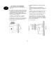
10.7 Fitting and connecting a
loudspeaker
An optional 16Ohm loudspeaker is connected to the
contacts
LS and +.
The loudspeaker can be integrated directly in the housing
of the alarm centre.
Alternatively, the loudspeaker can be mounted as an
additional internal alarm away from the alarm centre. The
distance from the alarm centre should not exceed 20m.
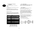
Additional alarm outputs
At the top of the PCB, the alarm centre has contacts for
additional transistor outputs. The cable supplied is
connected to these contacts. The cable pin connection is
described in the following. Note that the colour code of the
cable is not always the same as described below.
Colour
Function
Red (1) +12V permanent
power supply (500mA max.)
Black (2) Ground 0V permanent
Orange/white (3) Not used
Brown/white (4) Fault input of telephone in the case
of line loss (+12V if faulty)
Grey (5) Additional output 8
White (6) Additional output 7
Violet (7) Additional output 6
Blue (8) Additional output 5
Green (9) Additional output 4
Yellow (10) Additional output 3
Orange (11) Additional output 2
Brown (12) Additional output 1
10.8 Relay module
Instead of using the additional transistor outputs, you can
connect an optional relay module with eight changer
relays. Note the information in the relay module.
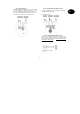
10.9 Resistors
The alarm system can monitor the zones in two ways.
A: Zone closed NC (no resistor inserted)
B: Zone closed 2.2 kOhm (two resistors inserted)
In Variant A, the system can only detect whether the zone
is opened and it always registers an opening as an alarm
in this zone. The tamper contacts of the individual
detectors must be connected separately to the tamper
zone of the alarm centre. The connection examples
described in these instructions refer to Variant A (without
resistors).
In Variant B, the tamper contact and alarm contact are
monitored in one zone. In the event of a change of
resistance, the alarm centre can distinguish whether it is a
case of alarm or tampering. Note that there are two
different resistance values:
A: 2.2 kOhm (red, red, red, gold)
B: 4.7 kOhm (yellow, violet, red, gold)
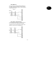
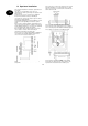
Note the two variants built in to the detector:
A: B:
2,2
kO
h
A
larm-
contact
4,7kOh
4.7kOh
Sabotage
contact
Sabotage-
contact
2,2
kO
h
A
larm-
contact