
Switch User Manual

EtherHub-16 Quick Start Guide
2
2. If you are making a connection to an end-node device (e.g., a PC or server), be sure that it has
a properly installed 10BASE-T network interface card. Attach one end of a straight-through
twisted-pair cable to an standard port (Port 1 ~ 16MDI-X) on the hub and the other end to the
RJ-45 port of the device’s network interface card. When inserting an RJ-45 plug, be sure the
tab on the plug clicks into position, to ensure that it is properly seated. Using the hub in a
stand-alone configuration, you can network up to 16 workstations.
3. Port 16MDI can be connected to a networking device such as a another compatible hub or a
switch. Run straight-through cable from Port 16MDI on this hub to a standard (
MDI-X) port
on the other device. (When attaching the hub to a bridge or router, verify the port type
implemented on these devices before connecting any cabling.)
Note: If necessary, you may also cascade from the MDI port on another device to the MDI-X on
this hub. Limit the number of hubs cascaded together is four, and be sure you do not create
any loops in your network connections.
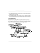
Connecting to an Ethernet Backbone
Thin Ethernet - Plug the BNC T-type connector into a BNC port on the hub, and use this port to
connect the hub to a 10BASE2 thin Ethernet trunk. If the unit is at the terminal end of a trunk
segment, then connect a 50-ohm (Ω) terminator to the open end of the “T” connector. If the BNC
port has no connection, plug in the T-type connector and lock both ends with a 50 Ω terminator.
Thick Ethernet - Attach an AUI to 10BASE5 transceiver to the thick Ethernet trunk, and then run
an AUI drop cable (with 15-pin D-type connectors on both ends) between an AUI port of the hub
and the transceiver. Note that the maximum length of an AUI drop cable is 50 meters (164 feet).
Fiber Optic - If you plan to use an AUI port for connecting fiber optic cable, attach a fiber optic
transceiver (MAU) to an AUI port, and then connect the transceiver to the fiber optic backbone.
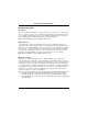
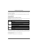
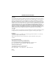
To specify the port types used on the rear panel, position the switches as indicated below:
Port 2 Port 1 Switch
BNC BNC
ON
2 3 4 1
F
Also note that if your transceiver provides an SQE
(Signal Quality Error) test, then it must be disabled.
BNC AUI
1 2 3 4
ON
AUI BNC
ON
1 2 3 4
AUI AUI
ON
1 2 3 4