
Instruction Manual

Installation for UL 762 Restaurant
Exhaust
• All units used in applications with grease laden air
are to be installed in accordance to NFPA 96, IMC
2203 and local codes. Consult local code authorities
for your specific requirements.
• Fans shall be located in an easily accessible area
of adequate size to allow for service or removal.
Exhaust fans with ductwork connected to both ends
shall have access for cleaning and inspection within
3 ft. (0.92 m) of each end of the fan (NFPA 96 –
Standard for Ventilation Control and Fire Protection
of Commercial Cooking Operations).
• Maintain a minimum clearance of at least 18inches
(457 mm) to combustible material and 6 inches
(125.4 mm) to either limited-combustible or
noncombustible material (NFPA 96).
• Fans are to be installed with the motors in the 3 or
9 o’clock (C or G) positions. Motors located in this
configuration may cause an unbalanced load that
should be considered if isolators are to be used.
Equalized loading between isolators can be achieved
through the use of mounting rails.
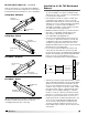
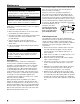
• It is recommended to install the fan near the end
of the duct run. This limits the amount of positive
pressure in the system. The diagram below illustrates
an inline fan exhausting air near the final termination
point. See local codes and NFPA 96 for any
restrictions and requirements for wall terminations.
• A drain is provided for single-point drainage of water
and residue. When installed correctly, housing drains
will be located on the bottom. This drain is used to
remove any accumulated grease and / or cleaning
solutions. Some means for collection of this residue
must be provided, either a container directly under
the drain or use an adapter and pipe to carry the
residue to a remote collection point. Remove drain
plug prior to connection to grease collection device.
• Provision to open and remove the access door is
required for periodic cleaning and maintenance. The
access door is clearly labeled and indicates that
access to this location must be maintained. Any
enclosure openings required to reach the access
panel shall be large enough to allow for the removal
of the panel.
Airflow
Minimum duct
at discharge
Exhaust air
exiting the
building
Exterior
Wall
Fan
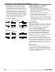
After mounting the fan to the rails, remaining mounting
hardware is installed in unused holes located in
overlapping sides (two piece rails only).
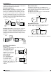
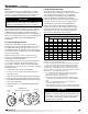
Rails are designed to accommodate fan installations
in a vertical or horizontal configuration. See the figures
below illustrating rail orientation for each configuration.
Mounting Rails (Optional) - continued
Ceiling Hung - Horizontal
Fan Mounting
Holes
Mounting
Hardware Holes
Ceiling Hung - Vertical
Fan Mounting
Holes
Mounting
Hardware Holes
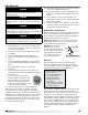
Base Mount - Horizontal
Fan Mounting
Holes
Mounting
Hardware Holes
Base Mount - Vertical
Fan Mounting
Holes
Mounting
Hardware Holes
Mixed Flow6