
Instruction Manual
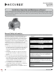

Cleaning, Maintenance and Repair
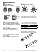
Cleaning of Internal Components
• Entire wheel should be cleaned during routine
duct cleaning. Partial cleaning may result in an
unbalanced wheel that can cause premature bearing
failure or excessive vibration.
• Grease / cleaning solution should drain freely
through the provided drain connection. Remove any
obstructions inhibiting proper drainage.
• Only the access door is removed during routine duct
cleaning. The bearing cover is not removed during
routine cleaning. The bearing cover is removed only
when inspecting or changing the bearings, fan shaft
or driven pulley.
Bearing Lubrication
See bearing manufacturer’s instructions or label on the
fan housing for lubrication schedule. Lubricate bearings
with high temperature grease conforming to NLGI
Grade2 such as Mobil Mobilith SHC 100 or 200.
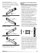
Sealant / Gasket / Seal Replacement
Fan to Duct Sealant / Gasket Replacement - Repair
or replace sealant / gasket as needed. Replacement
sealant or gasket shall be rated for 1500ºF (815º C)
and shall be grease tight such as 3M Fire Barrier
2000+ Silicone Sealant. See Sealant and Overlapping
Connection figures for proper installation.
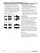
Access Door / Bearing Cover Gasket Replacement -
Replace access door or bearing cover gasket material
as needed. Gasket material for the access door is 1/2 x
1/2 inch (12.7 x 12.7 mm) part number 220145. Gasket
for the bearing cover is 1/8 x 1/2 inch (3.17 x 12.7 mm)
part number 220144. Both items are ordered by the
foot.
Mechanical Seal
A mechanical seal, located inside the bearing cover,
is used to keep grease from penetrating into this area.
Contact your local sales representative with the fan’s
serial number for appropriate sizing and part number for
a replacement mechanical seal.
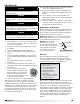
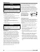
Installation for UL 762 Restaurant Exhaust - continued
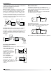
• Inline fans shall be connected to the exhaust
duct by flanges securely bolted as shown in the
figures below (NFPA 96 – Standard for Ventilation
Control and Fire Protection of Commercial Cooking
Operations). Flexible connectors shall not be used.
Units supplied with matching companion flanges are
to have this part welded to the ductwork and then
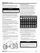
bolted to the fan. Gaskets used in the Overlapping
Connection style shall not be positioned in a manner
to have direct contact with the grease. Connection
hardware and gasketing are field supplied.
Fan
Flange
Gasket rated for
1500°F (815°C)
1/4 inch (6.25 mm) carbon
or stainless steel bolts
1/4 inch (6.25 mm) carbon
or stainless steel bolts
Welded Companion Flange
or 1 x 1 x 1/4 inch (25.4 x
25.4 x 6.25 mm) angle
Fan
Flange
Sealant rated for
1500°F (815°C)
Minimum 1 inch
(25.4 mm) flange
Airflow
Overlapping Connection
Sealant Connection
Mixed Flow 7