
Manual


Installation Instructions
1-1/2” Bore Adjustable Shock Absorber
23435 Industrial Park Drive
Farmington Hills, Michigan 48335
tel: 248.476.0213
fax: 248.476.2470
www.acecontrols.com
Maximum efficiency of operation can be obtained by
carefully following these instructions:
GENERAL
Install the adjustable shock absorber (Figure 1) on a
surface of sufficient strength. Align the shock absorber rod
end button with the load striking surface. This avoids side
0
loading (5 maximum). Use the full stroke of the shock
absorber up to the last 3/32 inch (2.5 mm) and provide a
solid mechanical stop to prevent bottoming out. To allow
maximum heat dissipation, DO NOT PAINT THE SHOCK
ABSORBER. If necessary, guard the shock absorber to
protect it from foreign materials such as acids, steam, weld
flash, etc. Applications using two or more adjustable shock
absorbers should have the load balanced between them as
equally as possible.
SELF-CONTAINED MODEL INSTALLATION
Model SAHS or AAHS adjustable shock absorbers are
pre-filled with American Industrial Oil #46 and are ready for
use after proper installation.
AIR-OIL TANK INSTALLATION
Model AHS or AHSS adjustable shock absorbers are
pre-filled with American Industrial Oil #46 but MUST BE
CONNECTED TO AN AIR-OIL TANK before use. Install
(Figure 2) the proper ACE air-oil tank as close as possible
to, and physically higher than, the shock absorber. The
line connecting the shock absorber to the air-oil tank must
be free of kinks and loops - and the inside diameter of this
line must be equal to, or greater than, that of the port in
the shock absorber. Do not put a shut off valve or a check
valve between the shock absorber and the air-oil tank.
Install a check valve in the air line to the air-oil tank and
plug the extra ports of the tank. Fill the tank with American
Industrial Oil #46 (taking care to avoid overfilling) and
charge the system to between 50 - 100 psi.
SIDE (FOOT) MOUNTING INSTALLATION (Figure 3)
Bolt the shock absorber to the mounting structure using
bolts as listed. Be sure to securely tighten the bolts.
PROVIDE A KEY BEHIND THE REAR FOOT BAR TO
PREVENT MOVEMENT OF THE SHOCK ABSORBER.
Bore
1-1/2
Bolt Size
(4) 1/2
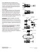
Air-Oil Tank
AO-3 or AO-6-91
Load
Flange
Stroke
-3/32”
Mechanical Stop
3/4” Minimum
Figure 1
Free Flow
Air-Oil Tank
Pressure
Regulator
Check
Valve
Fill
Plug
Bleed
Screw
Inlet
Port
Adjusting Ring
Graduated Dial
Figure 2
Welded Key
Figure 3
World leader in deceleration technology
ISO 9001:2000 Certified
ACE Controls Inc.