HARDWARE GUIDE MegaRAID® SCSI 320-0 Zero-Channel RAID Controller September 2002 ®
This document contains proprietary information of LSI Logic Corporation. The information contained herein is not to be used by or disclosed to third parties without the express written permission of an officer of LSI Logic Corporation. LSI Logic products are not intended for use in life-support appliances, devices, or systems. Use of any LSI Logic product in such applications without written consent of the appropriate LSI Logic officer is prohibited.
FCC Regulatory Statement This device complies with Part 15 of the FCC Rules. Operation is subject to the following two conditions: (1) this device may not cause harmful interference, and (2) this device must accept any interference received, including interference that may cause undesired operation. Warning: Changes or modifications to this unit not expressly approved by the party responsible for compliance could void the user's authority to operate the equipment.
iv Copyright © 2002 by LSI Logic Corporation. All rights reserved.
Preface This book is the primary reference and Hardware Guide for the LSI Logic MegaRAID® SCSI 320-0 Controller. It contains instructions for installing the MegaRAID controller and for configuring RAID arrays. It also contains background information on RAID. The MegaRAID SCSI 320-0 controller supports single-ended and lowvoltage differential (LVD) SCSI devices on an Ultra320 and Wide SCSI channel with data transfer rates up to 320 Mbytes/s.
· Chapter 6, Hardware Installation, explains how to install the MegaRAID SCSI 320-0 controller. · Chapter 7, Troubleshooting, provides troubleshooting information for the MegaRAID SCSI 320-0 controller. · Appendix A, Audible Warnings, explains the meaning of the warning tones generated by the MegaRAID SCSI 320-0 RAID controller.
MegaRAID Problem Report Form (Cont.) MegaRAID Driver Ver.: CPU Type/Speed: Network Card: System Memory: Other disk controllers installed: Other adapter cards Installed: Description of problem: Steps necessary to re-create problem: 1. 2. 3. 4. Logical Drive Configuration Use this form to record the configuration details for your logical drives.
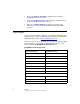
Logical Drive Configuration (Cont.) Logical Drive RAID Level Stripe Size Logical Drive Size Cache Policy Read Policy LD9 LD10 LD11 LD12 LD13 LD14 LD15 LD16 LD17 LD18 LD19 LD20 LD21 LD22 LD23 LD24 LD25 LD26 LD27 LD28 LD29 LD30 LD31 LD32 LD33 viii Preface Copyright © 2002 by LSI Logic Corporation. All rights reserved.
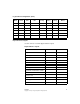
Logical Drive Configuration (Cont.) Logical Drive RAID Level Stripe Size Logical Drive Size Cache Policy Read Policy Write Policy # of Physical Drives LD34 LD35 LD36 LD37 LD38 LD39 Physical Device Layout Use this form to record the physical device layout.
Physical Device Layout (Cont.
Physical Device Layout (Cont.
Physical Device Layout (Cont.) Channel 0 Manufacturer/Model number Firmware level Target ID Device type Logical drive number/Drive number Manufacturer/Model number Firmware level Target ID Device type Logical drive number/Drive number Manufacturer/Model number Firmware level xii Preface Copyright © 2002 by LSI Logic Corporation. All rights reserved.
Contents Chapter 1 Overview 1.1 1.2 1.3 1.4 1.5 1.6 Chapter 2 Introduction to RAID 2.1 2.2 2.3 Features NVRAM and Flash ROM Single-Ended and Differential SCSI Buses Maximum Cable Length for SCSI Standards SCSI Bus Widths and Maximum Throughput Documentation 1.6.1 MegaRAID SCSI 320-0 ZCR Hardware Guide 1.6.2 MegaRAID Configuration Software Guide 1.6.3 MegaRAID Operating System Driver Installation Guide 1-2 1-2 1-2 1-3 1-4 1-4 1-4 1-4 RAID Benefits 2.1.1 Improved I/O 2.1.
2.3.8 2.3.9 2.3.10 2.3.11 2.3.12 2.3.13 2.3.14 2.3.15 Parity Hot Spares Hot Swapping Disk Rebuild Logical Drive States SCSI Drive States Disk Array Types Enclosure Management 2-8 2-8 2-9 2-9 2-10 2-10 2-11 2-11 Chapter 3 RAID Levels 3.1 3.2 3.3 3.4 3.5 3.6 Selecting a RAID Level RAID 0 RAID 1 RAID 5 RAID 10 RAID 50 3-1 3-2 3-3 3-4 3-6 3-7 4.1 4.2 4.3 4.4 4.5 4.6 4.7 4.8 4.
4.11 4.10.4 MegaRAID Manager Compatibility 4.11.1 Server Management 4.11.2 SCSI Device Compatibility 4.11.3 Software Chapter 5 Configuring Physical Drives, Arrays, and Logical Drives 5.1 Configuring SCSI Physical Drives 5.1.1 Basic Configuration Rules 5.1.2 Current Physical Device Configuration 5.1.3 Logical Drive Configuration 5.1.4 Physical Device Layout 5.2 Configuring Arrays 5.2.1 Arranging Arrays 5.2.2 Creating Hot Spares 5.3 Creating Logical Drives 5.3.1 Configuration Strategies 5.3.
Chapter 7 Troubleshooting 7.1 7.2 7.3 7.4 General Troubleshooting BIOS Boot Error Messages Other BIOS Error Messages Other Potential Problems Appendix A Audible Warnings Appendix B Glossary Index Customer Feedback xvi Contents Copyright © 2002 by LSI Logic Corporation. All rights reserved.
Chapter 1 Overview This chapter provides an overview of the MegaRAID® SCSI 320-0 and basic SCSI features. It contains the following sections: · Section 1.1, “Features” · Section 1.2, “NVRAM and Flash ROM” · Section 1.3, “Single-Ended and Differential SCSI Buses” · Section 1.4, “Maximum Cable Length for SCSI Standards” · Section 1.5, “SCSI Bus Widths and Maximum Throughput” · Section 1.
1.1 Features MegaRAID SCSI 320-0 features include: 1.2 · Provides a high performance I/O migration path while preserving existing PCI-SCSI software. · Performs SCSI data transfers up to 320 Mbytes/s. · Performs synchronous operation on a wide low-voltage differential (LVD) SCSI bus. · Allows up to 15 LVD SCSI devices on the wide bus. · Includes an Intel GC80302 integrated I/O processor that performs RAID calculations and routing.
1.4 Maximum Cable Length for SCSI Standards Table 1.1 lists the maximum SCSI cable length and number of disk drives that you can use, depending on the SCSI speeds. Table 1.1 Maximum Cable Length for SCSI Standards Standard Single Ended SCSI Low-Voltage Differential SCSI Maximum # of Drives Ultra SCSI 1.5 m 12 m 7 Ultra SCSI 3m 12 m 3 12 m 15 Wide Ultra SCSI Wide Ultra SCSI 1.
1.5 SCSI Bus Widths and Maximum Throughput Table 1.2 lists the SCSI bus widths and maximum throughput, based on the SCSI speeds. Table 1.2 1.6 SCSI Bus Widths and Maximum Throughput SCSI Standard SCSI Bus Width SCSI Throughput Fast Wide SCSI 16 bits 20 Mbytes/s Wide Ultra SCSI 16 bits 40 Mbytes/s Wide Ultra 2 SCSI 16 bits 80 Mbytes/s Wide Ultra 160 SCSI 16 bits 160 Mbytes/s Ultra 320 SCSI 16 bits 320 Mbytes/s Documentation The MegaRAID SCSI 320-0 documentation set includes: 1.6.
1.6.3 MegaRAID Operating System Driver Installation Guide This manual provides detailed information about installing the MegaRAID SCSI 320-0 operating system drivers. Documentation Copyright © 2002 by LSI Logic Corporation. All rights reserved.
1-6 Overview Copyright © 2002 by LSI Logic Corporation. All rights reserved.
Chapter 2 Introduction to RAID This chapter introduces important RAID concepts. It contains the following sections: · Section 2.1, “RAID Benefits” · Section 2.2, “MegaRAID SCSI 320-0 – Host-Based RAID Solution” · Section 2.3, “RAID Overview” RAID (Redundant Array of Independent Disks) is a data storage method in which data, along with parity information, is distributed among two or more hard disks (called an array) to improve performance and reliability.
2.1.2 Increased Reliability The electromechanical components of a disk subsystem operate more slowly, require more power, and generate more noise and vibration than electronic devices. These factors reduce the reliability of data stored on disks. RAID provides a way to achieve much better fault tolerance and data reliability. 2.2 MegaRAID SCSI 320-0 – Host-Based RAID Solution RAID products are either host-based or external. The MegaRAID SCSI 320-0 controller is a host-based RAID solution.
2.2.2 SCSI-to-SCSI External RAID A SCSI-to-SCSI external RAID product puts the RAID intelligence inside the RAID chassis and uses a plain SCSI host adapter installed in the network server. The data transfer rate is limited to the bandwidth of the SCSI channel. A SCSI-to-SCSI external RAID product that has two wide SCSI channels operating at speeds up to 320 Mbytes/s must squeeze the data into a single wide SCSI (320 Mbytes/s) channel back to the host computer.
· 2.3.3 A combination of any two of the above conditions Consistency Check A consistency check verifies the correctness of redundant data in a RAID array. For example, in a system with distributed parity, checking consistency means computing the parity of the data drives and comparing the results to the contents of the parity drives. 2.3.
Figure 2.1 Disk Striping MegaRAID Controller Segment 1 Segment 5 Segment 9 Segment 2 Segment 6 Segment 10 Segment 3 Segment 7 Segment 11 Segment 4 Segment 8 Segment 12 Disk striping involves partitioning each disk drive’s storage space into stripes that can vary in size from 2 to 128 Kbytes. These stripes are interleaved in a repeated, sequential manner. The combined storage space is composed of stripes from each drive. MegaRAID SCSI 320-0 supports stripe sizes of 2, 4, 8, 16, 32, 64, or 128 Kbytes.
2.3.5.2 Stripe Size The stripe size is the length of the interleaved data segments that MegaRAID SCSI 320-0 writes across multiple drives. MegaRAID SCSI 320-0 supports stripe sizes of 2, 4, 8, 16, 32, 64, or 128 Kbytes. 2.3.6 Disk Mirroring With disk mirroring (used in RAID 1), data written to one disk drive is simultaneously written to another disk drive, as shown in Figure 2.2. Figure 2.
2.3.7 Disk Spanning Disk spanning allows multiple disk drives to function like one big drive. Spanning overcomes lack of disk space and simplifies storage management by combining existing resources or adding relatively inexpensive resources. For example, four 60 Gbyte disk drives can be combined to appear to the operating system as one single 240 Gbyte drive. Disk spanning alone does not provide reliability or performance enhancements.
Table 2.1 describes how disk spanning is used for RAID 10 and RAID 50. Table 2.1 Spanning for RAID 10 and RAID 50 Level Description 10 Configure RAID 10 by spanning two contiguous RAID 1 logical drives. The RAID 1 logical drives must have the same stripe size. 50 Configure RAID 50 by spanning two contiguous RAID 5 logical drives. The RAID 5 logical drives must have the same stripe size. Note: 2.3.
has a capacity closest to and at least as great as that of the failed drive to take the place of the failed drive. Note: Hot spares are employed only in arrays with redundancy— for example, RAID levels 1, 5, 10, and 50. A hot spare connected to a specific MegaRAID SCSI 320-0 controller can be used only to rebuild a drive that is connected to the same controller. 2.3.10 Hot Swapping Hot swapping is the manual replacement of a defective physical disk unit while the computer is still running.
The MegaRAID SCSI 320-0 rebuild rate can be configured between 0% and 100%. At 0%, the rebuild is only done if the system is not doing anything else. At 100%, the rebuild has a higher priority than any other system activity. 2.3.12 Logical Drive States Table 2.2 describes the logical drive states. Table 2.2 Logical Drive States State Description Optimal The drive operating condition is good. All configured drives are online. Degraded The drive operating condition is not optimal.
2.3.14 Disk Array Types Table 2.4 describes the RAID disk array types. Table 2.4 Disk Array Types Type Description SoftwareBased The array is managed by software running in a host computer using the host CPU bandwidth. The disadvantages associated with this method are the load on the host CPU and the need for different software for each operating system. SCSI to SCSI The array controller resides outside of the host computer and communicates with the host through a SCSI adapter in the host.
2-12 Introduction to RAID Copyright © 2002 by LSI Logic Corporation. All rights reserved.
Chapter 3 RAID Levels This chapter describes each supported RAID level and the factors to consider when choosing a RAID level. It contains the following sections: 3.1 · Section 3.1, “Selecting a RAID Level” · Section 3.2, “RAID 0” · Section 3.3, “RAID 1” · Section 3.4, “RAID 5” · Section 3.5, “RAID 10” · Section 3.6, “RAID 50” Selecting a RAID Level To ensure the best performance, you should select the optimal RAID level when you create a system drive.
3.2 RAID 0 RAID 0 provides disk striping across all drives in the RAID subsystem. RAID 0 does not provide any data redundancy, but does offer the best performance of any RAID level. RAID 0 breaks up data into smaller blocks and then writes a block to each drive in the array. The size of each block is determined by the stripe size parameter, set during the creation of the RAID set. RAID 0 offers high bandwidth.
Figure 3.1 RAID 0 Array MegaRAID Controller Segment 1 Segment 5 Segment 9 3.3 Segment 2 Segment 6 Segment 10 Segment 3 Segment 7 Segment 11 Segment 4 Segment 8 Segment 12 RAID 1 In RAID 1, the MegaRAID SCSI 320-0 duplicates all data from one drive to a second drive. RAID 1 provides complete data redundancy, but at the cost of doubling the required data storage capacity. Uses Use RAID 1 for small databases or any other environment that requires fault tolerance but small capacity.
Figure 3.2 RAID 1 Array MegaRAID Controller Segment 1 Segment 2 Segment 3 Segment 4 3.4 Segment 1 Duplicated Segment 2 Duplicated Segment 3 Duplicated Segment 4 Duplicated RAID 5 RAID 5 includes disk striping at the byte level and parity. In RAID 5, the parity information is written to several drives. RAID 5 is best suited for networks that perform many small I/O transactions simultaneously. RAID 5 addresses the bottleneck issue for random I/O operations.
Uses Provides high data throughput, especially for large files. Use RAID 5 for transaction processing applications, because each drive can read and write independently. If a drive fails, the MegaRAID SCSI 320-0 uses the parity data to recreate all missing information. Use also for office automation and online customer service that requires fault tolerance. Use for any application that has high read request rates but low write request rates.
3.5 RAID 10 RAID 10 is a combination of RAID 0 and RAID 1. RAID 10 has mirrored drives. RAID 10 breaks up data into smaller blocks, and then stripes the blocks of data to each RAID 1 RAID set. Each RAID 1 RAID set then duplicates its data to its other drive. The size of each block is determined by the stripe size parameter, which is set during the creation of the RAID set. RAID 10 can sustain one to four drive failures while maintaining data integrity, if each failed disk is in a different RAID 1 array.
Figure 3.4 RAID 10 Array MegaRAID Controller Data Flow RAID 1 Disk 1 Segment 1 Segment 3 Segment 5 RAID 1 Disk 2 Disk 3 Segment 2 Segment 4 Segment 6 Segment 1 Segment 3 Segment 5 Disk 4 Segment 2 Segment 4 Segment 6 RAID 0 3.6 RAID 50 RAID 50 provides the features of both RAID 0 and RAID 5, including both parity and disk striping across multiple drives. RAID 50 is best implemented on two RAID 5 disk arrays with data striped across both disk arrays.
RAID 50 can sustain one to four drive failures while maintaining data integrity, if each failed disk is in a different RAID 5 array. Uses Works best when used with data that requires high reliability, high request rates, high data transfer, and medium to large capacity. Strong Points Provides high data throughput, data redundancy, and very good performance. Weak Points Requires 2 to 4 times as many parity drives as RAID 5.
Chapter 4 Features This chapter explains the features of the MegaRAID SCSI 320-0. It contains the following sections: · Section 4.1, “SMART Technology” · Section 4.2, “Configuration on Disk” · Section 4.3, “Configuration Features” · Section 4.4, “Array Performance Features” · Section 4.5, “RAID Management Features” · Section 4.6, “Fault Tolerance Features” · Section 4.7, “Software Utilities” · Section 4.8, “Operating System Software Drivers” · Section 4.
4.2 Configuration on Disk Configuration on Disk (drive roaming) saves configuration information both in nonvolatile random access memory (NVRAM) on the MegaRAID SCSI 320-0, and on the disk drives controlled by the MegaRAID SCSI 320-0. If the MegaRAID SCSI 320-0 is replaced, the new MegaRAID SCSI 320-0 controller can detect the actual RAID configuration, maintaining the integrity of the data on each drive, even if the drives have changed channel and/or target ID. 4.3 Configuration Features Table 4.
Table 4.1 Configuration Features (Cont.) Specification Feature Online capacity expansion Yes Hot spare support Yes Flashable firmware Yes Hot swap devices supported Yes Non-disk devices supported Yes Mixed capacity hard disk drives Yes Support for hard disk drives with capacities of more than 8 Gbytes. Yes Clustering support (Failover control) No Online RAID level migration Yes RAID remapping Yes No reboot necessary after expansion Yes More than 200 Qtags per physical drive Yes 4.
4.5 RAID Management Features Table 4.3 lists the RAID management features. Table 4.3 4.6 RAID Management Features Specification Feature Support for SNMP Yes Performance Monitor provided Yes Remote control and monitoring Yes Support for concurrent multiple stripe sizes Yes Windows NT, 2000, XP, and .NET server support using a GUI client utility Yes Fault Tolerance Features Table 4.4 lists the fault tolerance features. Table 4.
4.7 Software Utilities Table 4.5 lists the software utility features. Table 4.5 4.8 Software Utilities Specification Feature Graphical user interface Yes Management utility Yes Bootup configuration using MegaRAID Manager Yes Online read, write, and cache policy switching Yes Operating System Software Drivers MegaRAID SCSI 320-1 includes a DOS software configuration utility, and drivers for: · Windows NT 4.0 · Windows 2000 · Windows .NET · Windows XP · Novell NetWare 5.1, 6.
4.9 MegaRAID SCSI 320-0 Specifications Table 4.6 lists the specifications for the SCSI 320-0. Table 4.6 MegaRAID SCSI 320-0 Specifications Parameter Specification Card size 2.536 x 6.6 inches (low-profile PCI) Processor Intel GC80302 integrated I/O processor Bus type PCI 2.2 PCI controller Intel GC80302 Bus data transfer rate Up to 132 Mbytes/s BIOS MegaRAID BIOS Cache configuration Predefined during manufacturing; ECC through a 66MHz 72-bit unbuffered 3.3V SDRAM.
4.9.2 Cache Memory MegaRAID SCSI 320-0 supports 32 to 128 Mbytes of ECC SDRAM DIMM on-board cache memory. MegaRAID supports write-through or write-back caching, which can be selected for each logical drive. To improve performance in sequential disk accesses, MegaRAID does not use read-ahead caching for the current logical drive. The default setting for the read policy is Normal, meaning no read-ahead caching. You can disable read-ahead caching. Warning: 4.9.
4.10 RAID Management RAID management is provided by software utilities that manage and configure the RAID system and MegaRAID SCSI 320-0, create and manage multiple disk arrays, control and monitor multiple RAID servers, provide error statistics logging, and provide online maintenance. They include: · MegaRAID BIOS Configuration Utility · WebBIOS Configuration Utility · Power Console Plus · MegaRAID Manager 4.10.
4.11 Compatibility MegaRAID SCSI 320-0 compatibility issues include: · Server management · SCSI device compatibility · Software compatibility 4.11.1 Server Management As a simple network management protocol (SNMP) agent, MegaRAID SCSI 320-0 supports all SNMP managers. 4.11.2 SCSI Device Compatibility MegaRAID SCSI 320-0 supports SCSI hard drives, CD drives, and tape drives. 4.11.3 Software All SCSI backup and utility software should work with MegaRAID SCSI 320-0.
4-10 Features Copyright © 2002 by LSI Logic Corporation. All rights reserved.
Chapter 5 Configuring Physical Drives, Arrays, and Logical Drives This chapter explains how to configure SCSI physical drives, arrays, and logical drives. It contains the following sections: 5.1 · Section 5.1, “Configuring SCSI Physical Drives” · Section 5.2, “Configuring Arrays” · Section 5.3, “Creating Logical Drives” · Section 5.4, “Configuring Logical Drives” · Section 5.
Note: 5.1.2 Be sure to back up your data regularly, even when using RAID. Current Physical Device Configuration Use Table 5.1 to describe the current configuration for your physical devices. Table 5.1 Physical Device Configuration SCSI ID Device Description 0 1 2 3 4 5 6 8 9 10 11 12 13 14 15 5-2 Configuring Physical Drives, Arrays, and Logical Drives Copyright © 2002 by LSI Logic Corporation. All rights reserved.
5.1.3 Logical Drive Configuration Use Table 5.2 to record the configuration for your logical drives. Table 5.2 Logical Drive Logical Drive Configuration RAID Level Stripe Size Logical Drive Size Cache Policy Read Policy Write Policy # of Physical Drives LD0 LD1 LD2 LD3 LD4 LD5 LD6 LD7 LD8 LD9 LD10 LD11 LD12 LD13 LD14 LD15 LD16 LD17 LD18 LD19 LD20 LD21 Configuring SCSI Physical Drives Copyright © 2002 by LSI Logic Corporation. All rights reserved.
Table 5.2 Logical Drive Logical Drive Configuration (Cont.) RAID Level Stripe Size Logical Drive Size Cache Policy Read Policy Write Policy LD22 LD23 LD24 LD25 LD26 LD27 LD28 LD29 LD30 LD31 LD32 LD33 LD34 LD35 LD36 LD37 LD38 LD39 5-4 Configuring Physical Drives, Arrays, and Logical Drives Copyright © 2002 by LSI Logic Corporation. All rights reserved.
5.1.4 Physical Device Layout Use Table 5.3 to record the physical device layout. Table 5.
Table 5.3 Physical Device Layout (Cont.
Table 5.3 Physical Device Layout (Cont.
Table 5.3 Physical Device Layout (Cont.) Channel 0 Channel 1 Target ID Device type Logical drive number/Drive number Manufacturer/Model number Firmware level 5.2 Configuring Arrays You organize the physical disk drives in arrays after they are connected to the SCSI channels controlled by the LSI Logic SCSI chip on the motherboard, and after they are formatted. An array can consist of up to 15 physical disk drives, depending on the RAID level. The MegaRAID SCSI 320-0 supports up to eight arrays.
You can designate drives as hot spares using the MegaRAID BIOS Configuration Utility, the MegaRAID Manager, or Power Console Plus. 5.3 Creating Logical Drives Logical drives are arrays or spanned arrays that are presented to the operating system. You must create one or more logical drives. The logical drive capacity can include all or any portion of an array. The logical drive capacity can also be larger than an array by using spanning. The MegaRAID SCSI 320-0 supports up to 40 logical drives. 5.3.
Table 5.4 RAID Level 5.3.1.2 Capacity for RAID Levels (Cont.) Description Drives Required Capacity 10 Mirroring and Striping 4 – 18 (Number of disks) X (capacity of (Must be a smallest disk) / (2) multiple of 2.) 50 RAID 5 and Striping 6 – 30 (Must be a multiple of arrays.
Table 5.6 Performance Characteristics for RAID Levels RAID Level 5.3.2 Performance Characteristics 0 Excellent for all types of I/O activity, but provides no data security. 1 Provides data redundancy and good performance. 5 Provides data redundancy and good performance in most environments. 10 Provides data redundancy and excellent performance. 50 Provides data redundancy and very good performance. Assigning RAID Levels Only one RAID level can be assigned to each logical drive. Table 5.
5.4 Configuring Logical Drives After you have installed the MegaRAID SCSI 320-0 controller in the server and have attached all physical disk drives, perform the following actions to prepare a RAID array: 1. Optimize MegaRAID SCSI 320-0 controller options for your system. See Chapter 6 for additional information. 2. Press to run the BIOS Configuration Utility. 3. If necessary, perform a low-level format of the SCSI drives that will be included in the array and the drives to be used for hot spares.
print servers? Does this disk array support any software system that must be available 24 hours per day? Will the information stored in this disk array contain large audio or video files that must be available on demand? Will this disk array contain data from an imaging system? You must identify the purpose of the data to be stored in the disk subsystem before you can confidently choose a RAID level and a RAID configuration. 5.5 Planning the Array Configuration Fill out Table 5.8 to help plan this array.
Use Table 5.9 to plan the array configuration. Table 5.
Table 5.9 Array Configuration Planner (Cont.) # of Drives Possible RAID Levels Relative Performance Fault Tolerance Effective Capacity 8 RAID 0 Excellent No 100% 8 RAID 5 Good Yes 87% 8 RAID 10 Good Yes 50% 8 RAID 50 Good Yes 75% Planning the Array Configuration Copyright © 2002 by LSI Logic Corporation. All rights reserved.
5-16 Configuring Physical Drives, Arrays, and Logical Drives Copyright © 2002 by LSI Logic Corporation. All rights reserved.
Chapter 6 Hardware Installation This chapter explains how to install the MegaRAID SCSI 320-0 controller. It contains the following sections: 6.1 · Section 6.1, “Hardware Requirements” · Section 6.2, “Installation Steps” · Section 6.
6.2 Installation Steps The MegaRAID SCSI 320-0 provides extensive customization options. If you need only basic MegaRAID SCSI 320-0 features and your computer does not use other adapter cards with resource settings that may conflict with MegaRAID SCSI 320-0 settings, even custom installation can be quick and easy. Table 6.1 lists the hardware installation steps. Each step is described in detail in the following pages. Table 6.1 Step 6.2.
· · 6.2.2 The Driver and Documentation CD, which contains these items: – The MegaRAID Configuration Software Guide – The MegaRAID Operating System Driver Installation Guide – The MegaRAID SCSI 320-0 ZCR Hardware Guide – The software license agreement – The MegaRAID SCSI 320-0 configuration utilities for DOS The warranty registration card Step 2: Power Down Turn off the computer, remove the power cord, then remove the cover.
Figure 6.1 MegaRAID SCSI 320-0 Controller Layout J2 J3 J4 Optional Backup Battery Unit J8 Connector 6.2.3.1 J2 Dirty Cache LED J2 is a two-pin header for the dirty cache LED. This can be connected to an LED on the computer enclosure. The LED will be lit when data in the cache has not yet been written to the storage device. 6.2.3.2 J3 Clear EPROM J3 is a two-pin header that clears the erasable progammable read-only memory (EPROM) configuration data. 6.2.3.
6.2.3.4 J8 Connector for Optional BBU Daughter Card J8 is 40-pin connector that is used to mount an optional battery backup unit that is on a daughtercard. 6.2.4 Step 4: Install MegaRAID SCSI 320-0 Select the ZCR 3.3 V or 5 V PCI slot and align the MegaRAID SCSI 320-0 controller bus connector with the slot. Figure 6.2 shows the differences between the 3.3 V and 5 V slots. Figure 6.2 Note: 3.
Figure 6.3 Installing the MegaRAID SCSI 320-0 Controller Bracket Screw 32-Bit Slots (3.3 V) 64-Bit Slots (5 V) 6.2.5 Step 5: Power Up Replace the computer cover and reconnect the AC power cords. Turn power on to the host computer. Set up the power supplies so that the SCSI devices are powered up at the same time as or before the host computer. If the computer is powered up before a SCSI device, the device might not be recognized.
The firmware takes several seconds to initialize. During this time the adapter will scan the SCSI channel(s). When ready, the following appears: Host Adapter-1 Firmware Version x.xx DRAM Size 16 MB 0 Logical Drives found on the Host Adapter 0 Logical Drives handled by BIOS Press to run MegaRAID SCSI 320-0 BIOS Configuration Utility The utility prompt times out after several seconds.
EMM386.EXE is loaded. If you do not do this, you cannot access the boot drive after EMM386 is loaded. 6.3 Summary This chapter discussed hardware installation. Configure the RAID system using software configuration utilities. See the MegaRAID Configuration Software Guide for all information about MegaRAID SCSI 320-0 software utilities. The utility programs for configuring MegaRAID SCSI 320-0 are shown in Table 6.4. Table 6.
Chapter 7 Troubleshooting This chapter provides troubleshooting information for the MegaRAID SCSI 320-0 controller. It contains the following sections: 7.1 · Section 7.1, “General Troubleshooting” · Section 7.2, “BIOS Boot Error Messages” · Section 7.3, “Other BIOS Error Messages” · Section 7.4, “Other Potential Problems” General Troubleshooting This section lists the general problems that can occur, along with suggested solutions. Table 7.
Table 7.1 General Problems and Suggested Solutions (Cont.) Problem Suggested Solution One of the hard drives in the array fails often. Check the drive error counts using Power Console Plus. See the MegaRAID Configuration Software Guide for more information. Format the drive. Rebuild the drive If the drive continues to fail, replace the drive with another drive with the same capacity. Pressed . Ran Megaconf.exe and tried to make a new configuration. The system hangs when scanning devices.
7.2 BIOS Boot Error Messages Table 7.2 describes error messages that can display when you boot the system, and suggested solutions. Table 7.2 BIOS Boot Error Messages Message Problem Suggested Solution Adapter BIOS Disabled. No Logical Drives Handled by BIOS The MegaRAID BIOS is disabled. Sometimes the BIOS is disabled to prevent booting from the BIOS. Enable the BIOS using the MegaRAID BIOS Configuration Utility.
Table 7.2 BIOS Boot Error Messages (Cont.) Message Problem Suggested Solution 1 Logical Drive Degraded A logical drive signed on in a degraded state. Make sure all physical drives are properly connected and are powered on. Run MegaRAID Manager to find out if any physical drives are not responding. Reconnect, replace, or rebuild any drive that is not responding. The following SCSI IDs are not responding: Channel x:a.b.c 7.
Table 7.3 Other BIOS Error Messages (Cont.) Message Problem Suggested Solution Unresolved configuration mismatch between disks and NVRAM on the adapter The configuration stored in the MegaRAID NVRAM does not match the configuration stored on the drives. 1. Press a key to run MegaRAID Manager. 2. Select View/Add Configuration from the Configure menu. 3. Use View/Add Configuration to examine both the configuration in NVRAM and the configuration stored on the disk drives. 4.
Table 7.4 Other Potential Problems (Cont.) Topic Information MegaRAID power requirements The maximum MegaRAID SCSI 320-0 power requirements are 15 W at 5 V and 3 A. SCSI bus requirements The ANSI specification dictates the following: · The maximum signal path length between terminators is 3 meters when using up to 4 maximum capacitance (25 pF) devices and 1.5 meters when using more than 4 devices.
Appendix A Audible Warnings The MegaRAID SCSI 320-0 RAID controller has an onboard tone generator that indicates events and errors. Note: Table A.1 This is available only if the optional series 502 Battery Backup Unit (BBU) is installed. Audible Warnings and Descriptions Tone Pattern Meaning Examples Three seconds on and one second off A logical drive is offline. One or more drives in a RAID 0 configuration failed. Two or more drives in a RAID 1, or 5 configuration failed.
A-2 Audible Warnings Copyright © 2002 by LSI Logic Corporation. All rights reserved.
Appendix B Glossary Array A grouping of individual disk drives that combines the storage space on the disk drives into a single segment of contiguous storage space. MegaRAID can group disk drives on one or more SCSI channels into an array. Array Management Software Software that provides common control and management for a disk array. Array management software most often executes in a disk controller or intelligent host bus adapter, but it can also execute in a host computer.
Channel An electrical path for the transfer of data and control information between a disk and a disk controller. Consistency Check An examination of the disk system to determine whether all conditions are valid for the specified configuration (such as parity.) Cold Swap A cold swap requires that you turn the power off before replacing a defective disk drive in a disk subsystem. Data Transfer Capacity The amount of data per unit time moved through a channel.
provides high I/O performance at low cost, but provides lowers data reliability than any of its member disks. Disk Subsystem A collection of disks and the hardware that connects them to one or more host computers. The hardware can include an intelligent controller, or the disks can attach directly to a host computer I/O bus adapter. Double Buffering A technique that achieves maximum data transfer bandwidth by constantly keeping two I/O requests for adjacent data outstanding.
Host Computer Any computer to which disks are directly attached. Mainframes, servers, workstations, and personal computers can all be considered host computers. Hot Spare A stand-by disk drive ready for use if a drive in an array fails. A hot spare does not contain any user data. Up to eight disk drives can be assigned as hot spares for an adapter. A hot spare can be dedicated to a single redundant array, or it can be part of the global hot-spare pool for all arrays controlled by the adapter.
Mbyte (Megabyte) An abbreviation for 1,000,000 (10 to the sixth power) bytes. One Mbyte equals 1,000 Kbytes (kilobytes). Multi-threaded Having multiple concurrent or pseudo-concurrent execution sequences. Used to describe processes in computer systems. Multi-threaded processes allow throughput-intensive applications to efficiently use a disk array to increase I/O performance.
RAID Redundant Array of Independent Disks. A data storage method in which data, along with parity information, is distributed among two or more hard disks (called an array) to improve performance and reliability. A RAID disk subsystem improves I/O performance on a server using only a single drive. The RAID array appears to the host server as a single storage unit. I/O is expedited because several disks can be accessed simultaneously. RAID Levels A style of redundancy applied to a logical drive.
Redundancy The provision of multiple interchangeable components to perform a single function to cope with failures or errors. Redundancy normally applies to hardware; disk mirroring is a common form of hardware redundancy. Replacement Disk A disk available to replace a failed member disk in a RAID array. Replacement Unit A component or collection of components in a disk subsystem that is always replaced as a unit when any part of the collection fails.
Service Provider The Service Provider (SP) is a program that resides in the desktop system or server and is responsible for all DMI activities. This layer collects management information from products (whether system hardware, peripherals, or software), stores that information in the DMI database, and passes it to management applications as requested. SNMP Simple Network Management Protocol.
Ultra320 A subset of Ultra3 SCSI that allows a maximum throughput of 320 Mbytes/s, which is twice as fast as Wide Ultra2 SCSI. Ultra320 SCSI provides 320 Mbytes/s on a 16-bit connection. Virtual Sizing FlexRAID virtual sizing is used to create a logical drive up to 80 Gbytes. A maximum of 40 logical drives can be configured on a RAID controller, and RAID migration is possible for all logical drives except the fortieth.
B-10 Glossary Copyright © 2002 by LSI Logic Corporation. All rights reserved.
Index A Array B-1 Array Configuration Planner 5-14 Array management software B-1 Array performance features 4-3 Array spanning B-1 Assigning RAID levels 5-11 Asynchronous operations B-1 Audible Warnings A-1 Automatic failed drive detection and rebuild 4-4 B E BIOS 4-6 BIOS Boot Error Messages 7-3 BIOS Configuration Utility 6-7 BIOS message 6-6 Bus data transfer rate 4-6 Bus type 4-6 Bus-based 2-11 C Cache configuration 4-6 Cache I/O B-1 Cache Memory 4-7 Card size 4-6 Channel B-2 Cold swap B-2 Compatibi
R Install Drivers 6-7 Installation steps Custom 6-2 Nonvolatile RAM 4-6 Novell NetWare 4-5, 6-7 NVRAM 1-2 RAID B-6 Benefits 2-1 Introduction to 2-1 RAID 0 3-2 RAID 1 3-3 Spanning to configure RAID 10 2-8 RAID 10 3-6 Configuring 2-8 RAID 5 3-4 Spanning to make RAID 50 2-8 RAID 50 3-7 Configuring 2-8 RAID benefits Improved I/O 2-1 Increased reliability 2-2 RAID levels 1-v, 3-1, B-6 RAID levels supported 4-6 RAID management 4-8 RAID management features 4-4 RAID migration B-6 RAID overview 2-3 Read-ahead B-6
Striping B-8 T Technical Support 1-vi Terminator B-8 Troubleshooting 7-1 U Ultra320 and Wide SCSI 4-1 Ultra3-SCSI (320M) B-9 Unpack 6-2 V Virtual sizing B-9 W WebBIOS Configuration Utility 4-8 Wide SCSI B-9 Windows .NET 6-7 Windows 2000 6-7 Windows NT 4-5, 6-7 Windows XP 6-7 Index Copyright © 2002 by LSI Logic Corporation. All rights reserved.
IX-4 Index Copyright © 2002 by LSI Logic Corporation. All rights reserved.
Customer Feedback We would appreciate your feedback on this document. Please copy the following page, add your comments, and fax it to us at the number shown. If appropriate, please also fax copies of any marked-up pages from this document. Important: Please include your name, phone number, fax number, and company address so that we may contact you directly for clarification or additional information. Thank you for your help in improving the quality of our documents.
Reader’s Comments Fax your comments to: LSI Logic Corporation Technical Publications M/S E-198 Fax: 408.433.4333 Please tell us how you rate this document: MegaRAID SCSI 320-0 Hardware Guide. Place a check mark in the appropriate blank for each category.